Fuel cell and electrolyte layer for fuel cell
An electrolyte layer and fuel cell technology, which is applied to fuel cell components, fuel cells, solid electrolyte fuel cells, etc., can solve problems such as interference with continuous power generation
- Summary
- Abstract
- Description
- Claims
- Application Information
AI Technical Summary
Problems solved by technology
Method used
Image
Examples
no. 2 approach
[0029]In the fuel cell of the first embodiment, the antifreeze protein is uniformly dispersed in the electrolyte layer 20 . In a variant, the antifreeze protein may only be present in certain subregions of the electrolyte layer. An example of this modified structure is described below as the second embodiment.
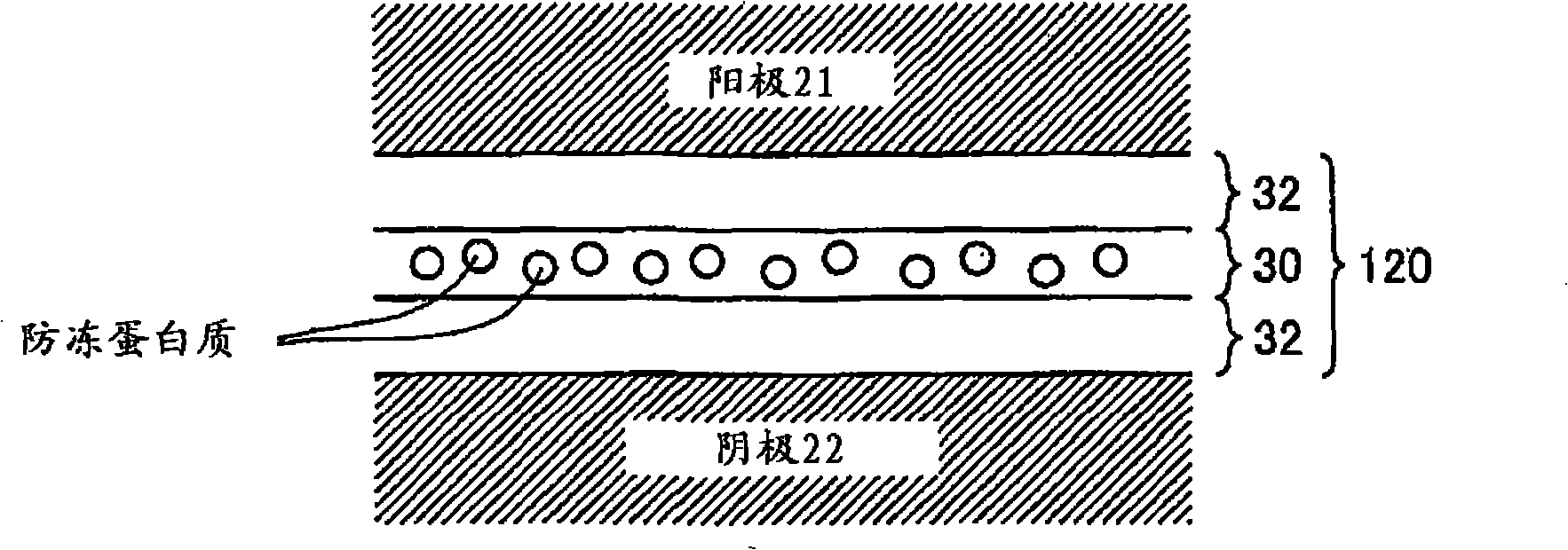
[0030] image 3 is a sectional view schematically showing the structure of the fuel cell of the second embodiment. The fuel cell of the second embodiment has a structure similar to that of the fuel cell of the first embodiment except that the electrolyte layer 20 is replaced by the electrolyte layer 120 . Similar elements are denoted by the same reference numerals and are not explained in detail here. image 3 The enlarged cross-sectional view of FIG. 1 shows only the region adjacent to the electrolyte layer 120.
[0031] In the fuel cell of the second embodiment, the electrolyte layer 120 includes the antifreeze protein-containing layer 30 having the antifreeze pr...
no. 3 approach
[0036] In the structure of the second embodiment, the antifreeze protein-containing layer 30 is located in the middle of the electrolyte layer 120 . In a variant, a layer containing antifreeze proteins can be provided on at least one surface of the electrolyte layer. An example of this modified structure is described below as a third embodiment. Figure 4 is a sectional view schematically showing the structure of the fuel cell in the third embodiment. The fuel cell of the third embodiment has a structure similar to that of the fuel cell of the second embodiment except that the electrolyte layer 120 is replaced with the electrolyte layer 220 having a different arrangement of the layer 30 containing the antifreeze protein and the layer 32 not containing the antifreeze protein Structure. Similar elements are denoted by the same reference numerals and are not explained in detail here. and image 3 similar, Figure 4 The enlarged cross-sectional view of FIG. 1 shows only the a...
PUM
| Property | Measurement | Unit |
|---|---|---|
| particle diameter | aaaaa | aaaaa |
| thickness | aaaaa | aaaaa |
Abstract
Description
Claims
Application Information
 - R&D
- Intellectual Property
- Life Sciences
- Materials
- Tech Scout
- Unparalleled Data Quality
- Higher Quality Content
- 60% Fewer Hallucinations
Browse by: Latest US Patents, China's latest patents, Technical Efficacy Thesaurus, Application Domain, Technology Topic, Popular Technical Reports.
© 2025 PatSnap. All rights reserved.Legal|Privacy policy|Modern Slavery Act Transparency Statement|Sitemap|About US| Contact US: help@patsnap.com


