Electric motor

A technology of motors and rotors, applied in the field of motors, can solve the problems of complicated motor control, reversal of size relationship, inability to control phase difference, etc.

Inactive Publication Date: 2009-01-07
HONDA MOTOR CO LTD
View PDF1 Cites 10 Cited by
  • Summary
  • Abstract
  • Description
  • Claims
  • Application Information

AI Technical Summary

Problems solved by technology

[0006] However, in the electric motor in an example of the above-mentioned prior art, for example, when controlling the phase difference between the first and second rotors according to the rotational speed of the electric motor, the second rotor can only be controlled under the condition that the centrifugal force acts on the operating state corresponding to the rotational speed of the electric motor. The phase difference between the first and second rotors sometimes has the problem of not being able to control the phase difference at an appropriate moment including the stop state of the motor
In addition, when the electric motor is mounted on a vehicle as a drive source, etc., in a state where external vibrations tend to act on the electric motor, it may be difficult to properly control the phases of the first and second rotors only by centrifugal force. bad question
Furthermore, in this case, although the phase difference is controlled against the fluctuation of the power supply voltage in the power supply of the motor, for example, there may be a problem that the magnitude relationship between the power supply voltage and the induced voltage of the motor is reversed.
[0007] In addition, for example, when the phase difference between the first and second rotors is controlled based on the speed of the rotating field generated by the stator, the speed of the rotating field is changed, so there is a problem that the control of the motor becomes complicated.

Method used


Image

  • Electric motor
  • Electric motor
  • Electric motor

Examples


Embodiment Construction

[0118] Next, an embodiment of a motor according to the present invention will be described with reference to the drawings.

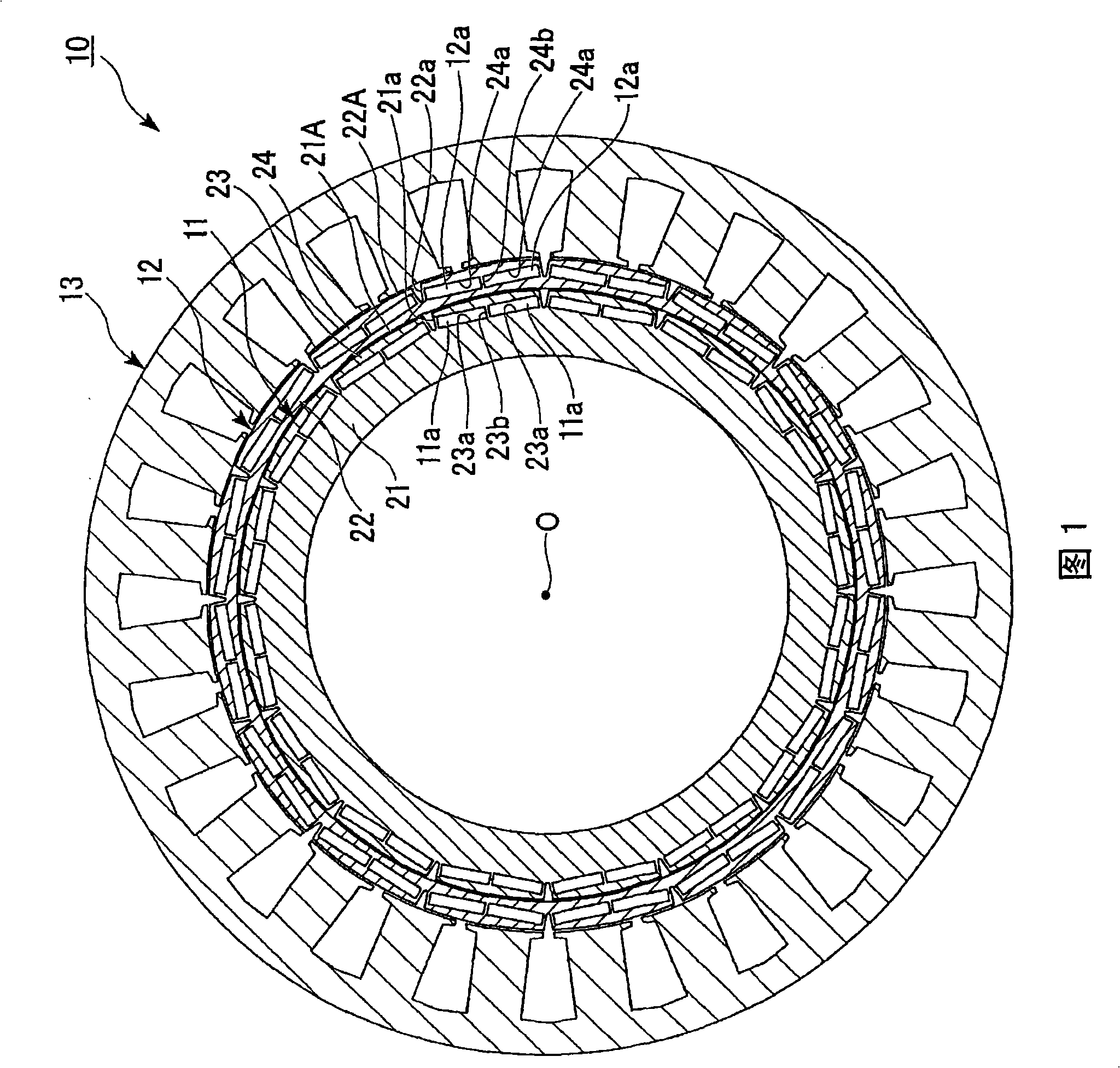
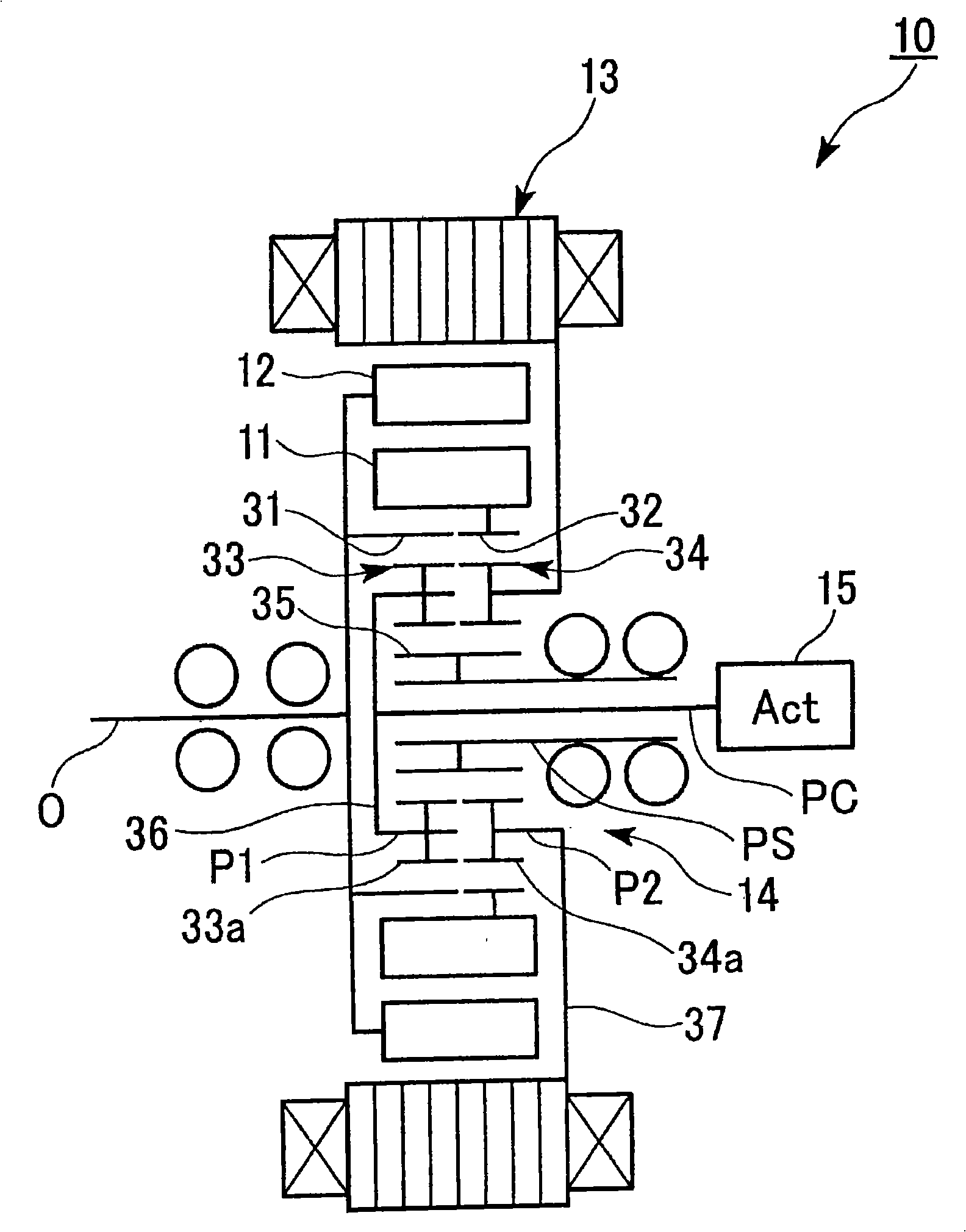
[0119] The motor 10 of the present embodiment is, for example, as shown in FIG. 1 , a brushless DC motor including substantially annular inner-circumferential rotors 11 and outer-circumferential rotors 11 provided with permanent magnets 11a and 12a arranged in the circumferential direction. rotor 12; a stator 13 having a plurality of phases of stator windings 13a that generate a rotating magnetic field that rotates the inner rotor 11 and the outer rotor 12; a planetary gear mechanism 14 that connects the inner rotor 11 and the outer rotor 12; The actuator 15 for setting the relative phase between the inner rotor 11 and the outer rotor 12 through the planetary gear mechanism 14 is mounted on a vehicle such as a hybrid vehicle or an electric vehicle as a drive source. An output shaft P of the electric motor 10 is connected to an input shaft of a transmissi...


PUM


Abstract

The invention provides an electric motor (10) which is constructed from an inner circumferential rotor (11) and an outer circumferential rotor (12) that are coaxially arranged and also from a planetary gear mechanism for rotating at least either the inner circumferential rotor (11) or the outer circumferential rotor (12) about a rotation axis (O). The motor is constructed such that, when at least either the inner circumferential rotor (11) or the outer circumferential rotors (12) is rotated by the planetary gear mechanism, a long side of a substantially oblong plate-shaped inner circumferential permanent magnet (11a) of the inner circumferential rotor (11) and a long side of a substantially oblong plate-shaped outer circumferential permanent magnet (12a) of the outer circumferential rotor (12) are opposite each other in a cross section in parallel to the rotation axis (O).

Description

technical field [0001] The present invention relates to electric motors. [0002] this application claims priority based on Japanese Patent Application No. 2005-367451 for which it applied in Japan on December 21, 2005, and uses the content here. Background technique [0003] Conventionally, there is known a motor that has, for example, first and second rotors arranged concentrically around the rotation shaft of the motor, and controls the first rotor according to the rotational speed of the motor or the speed of a rotating magnetic field generated by the stator. and the relative position in the circumferential direction of the second rotor, that is, the phase difference (for example, refer to Patent Document 1). [0004] In this motor, for example, when the phase difference between the first and second rotors is controlled according to the rotational speed of the motor, the relative positions of the first and second rotors in the circumferential direction are changed by a ...

Claims


Application Information

Patent Timeline
Patent Type & Authority Applications(China)
IPC IPC(8): H02K16/02H02K1/27
CPCH02K7/116H02K21/029H02K16/02
Inventor 新博文阿部升荣河村保佐藤浩光
Owner HONDA MOTOR CO LTD
Why Eureka
Try Eureka