Electromagnetic vibration table

An electromagnetic vibration and motion table technology, which is applied to fluids, measuring devices, instruments, etc. using vibration, can solve the problems such as the reduction of the output electromagnetic force of the vibration table, the easy distortion of the waveform, and the increase of the non-uniformity of the magnetic induction intensity. Distortion improvement and uniform magnetic field strength

Active Publication Date: 2009-01-14
ZHEJIANG UNIV +2
View PDF1 Cites 31 Cited by
  • Summary
  • Abstract
  • Description
  • Claims
  • Application Information

AI Technical Summary

Problems solved by technology

The electromagnetic vibrating table with a large stroke is required to have a longer magnetic gap length. If the magnetic circuit structure of the traditional electromagnetic vibrating table is adopted, the magnetic induction intensity will...

Method used


Image

  • Electromagnetic vibration table
  • Electromagnetic vibration table
  • Electromagnetic vibration table

Examples


Embodiment Construction

[0031] The present invention will be described in further detail below in conjunction with the accompanying drawings and specific embodiments.

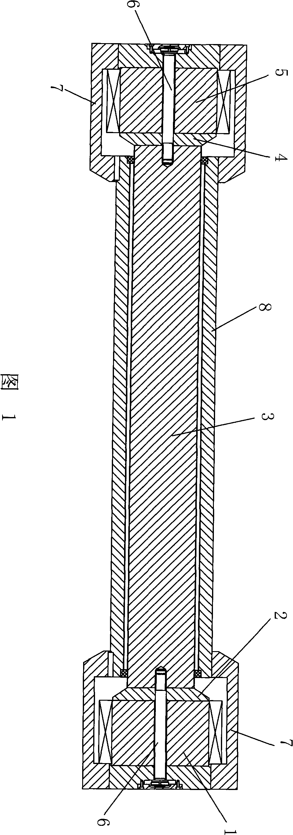
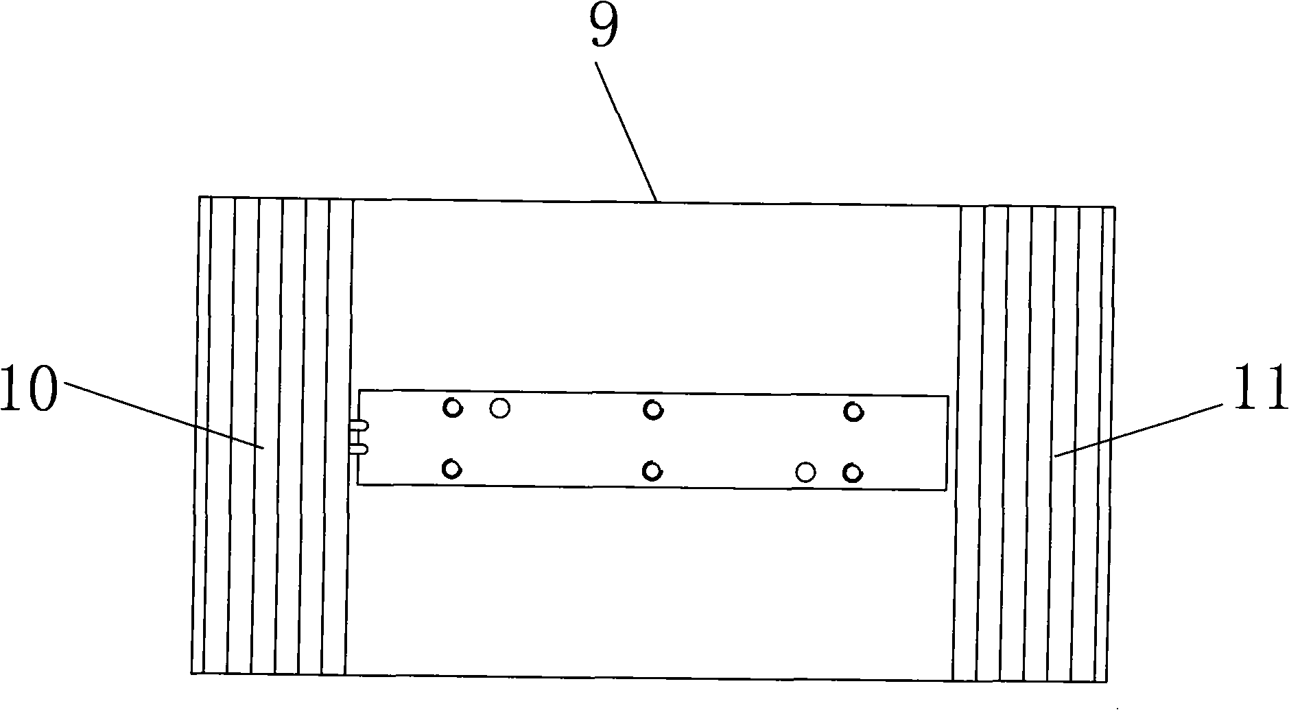
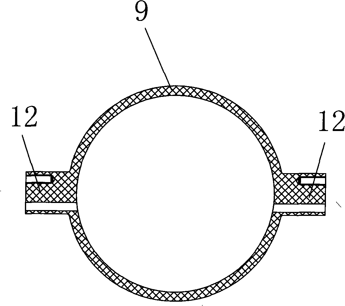
[0032] Refer to Figure 1~ Image 6 , an electromagnetic vibrating table, including a table body, and the table body includes a first magnet 1, a first transition block 2, a central magnetic guide column 3, a second transition block 4, and a second magnet 5 connected in sequence with coaxial lines The first magnet 1 and the second magnet 5 are respectively fixed in the end shell 7 by non-magnetically conductive bolts 6, and the first magnet 1 and the second magnet 5 are opposite to each other with the same magnetic poles, and the central magnetically conductive column 3 The outer coaxial sleeve is provided with an outer magnetic tube 8, the two ends of the outer magnetic tube 8 are respectively fastened to the end shell 7, the central magnetic column 3 and the outer magnetic tube 8 There is an air gap between them. In order to further...


PUM


Abstract

The present invention relates to an electromagnetic vibrating table, comprising a table body. The table body comprises a first magnet, a first transition block, a central magnetic conducting pole, a second transition block and a second magnet, and the central magnetic conducting pole is housed by a moving coil; the table body also comprises a moving table and two frame-shape air-bearing guide rails, and the moving table can be arranged in the air-bearing guide rails in a sliding manner; the table body also comprises a drive motor and a lead screw connected with the drive motor, the lead screw is connected with a base plate, and both the leading wire and the air pipe are connected with the base plate; a grating scale is also arranged on the air-bearing guide rails, a grating read head opposite to the grating scale and a communication block connected with the grating read head are also arranged on the moving table; the communication block is connected with a controller; and the drive motor is connected with the controller signal. The invention provides an electromagnetic vibrating table with a complete peripheral device; the motor is controlled by the controller to drive the lead screw to pull the base plate to make simultaneous movement following the moving table, thereby, the subsidiary load of the air inlet pipe and the electrified lead wire does not influence the big-travel and low-frequency waveform distortion degree of the vibrating table.

Description

(1) Technical field [0001] The invention relates to an electromagnetic vibrating table. (2) Background technology [0002] In dynamic measurement, due to the aging of the sensor crystal sheet, the accuracy of the sensor directly affects the accuracy of the measured parameters, so regular calibration of the vibration sensor's sensitivity, nonlinearity, frequency response and other technical parameters is the fundamental guarantee of measurement accuracy. The vibration table is the main component of the vibration sensor calibration equipment. At present, the electromagnetic vibration table is more commonly used and the technology in this area is relatively mature. Electromagnetic vibration has a history of about a hundred years since its birth, and its composition has not changed much. The structure of the magnetic circuit is composed of a single permanent magnet or exciter installed in a soft iron magnetizer, a central magnetic pole and a breath. The energized coil in the ga...

Claims


Application Information

Patent Timeline
IPC IPC(8): B06B1/04G01D18/00G01H17/00
Inventor 沈润杰贾叔仕徐佰万
Owner ZHEJIANG UNIV
Why Eureka
Try Eureka