
Polishing head

A polishing head and transmission disk technology, applied in the field of polishing head, can solve problems such as uneven removal rate, uneven polishing removal rate, uneven wafer surface, etc., and achieve global planarization, uniform polishing removal rate, and low resistance Effect

Active Publication Date: 2009-01-14
THE 45TH RES INST OF CETC
View PDF0 Cites 13 Cited by
  • Summary
  • Abstract
  • Description
  • Claims
  • Application Information

AI Technical Summary

Problems solved by technology

In the chemical mechanical polishing process, the polishing head plays the role of picking up the wafer and driving the wafer to rotate on the polishing pad for polishing. Due to the continuous increase in the size of the wafer and the uneven density of graphic lines, the polishing removal rate is uneven. situation, the unevenness of the removal rate causes the unevenness of the wafer surface

Method used


Image

  • Polishing head
  • Polishing head
  • Polishing head

Examples


Embodiment Construction

[0016] The present invention will be described in further detail below in conjunction with embodiment accompanying drawing:

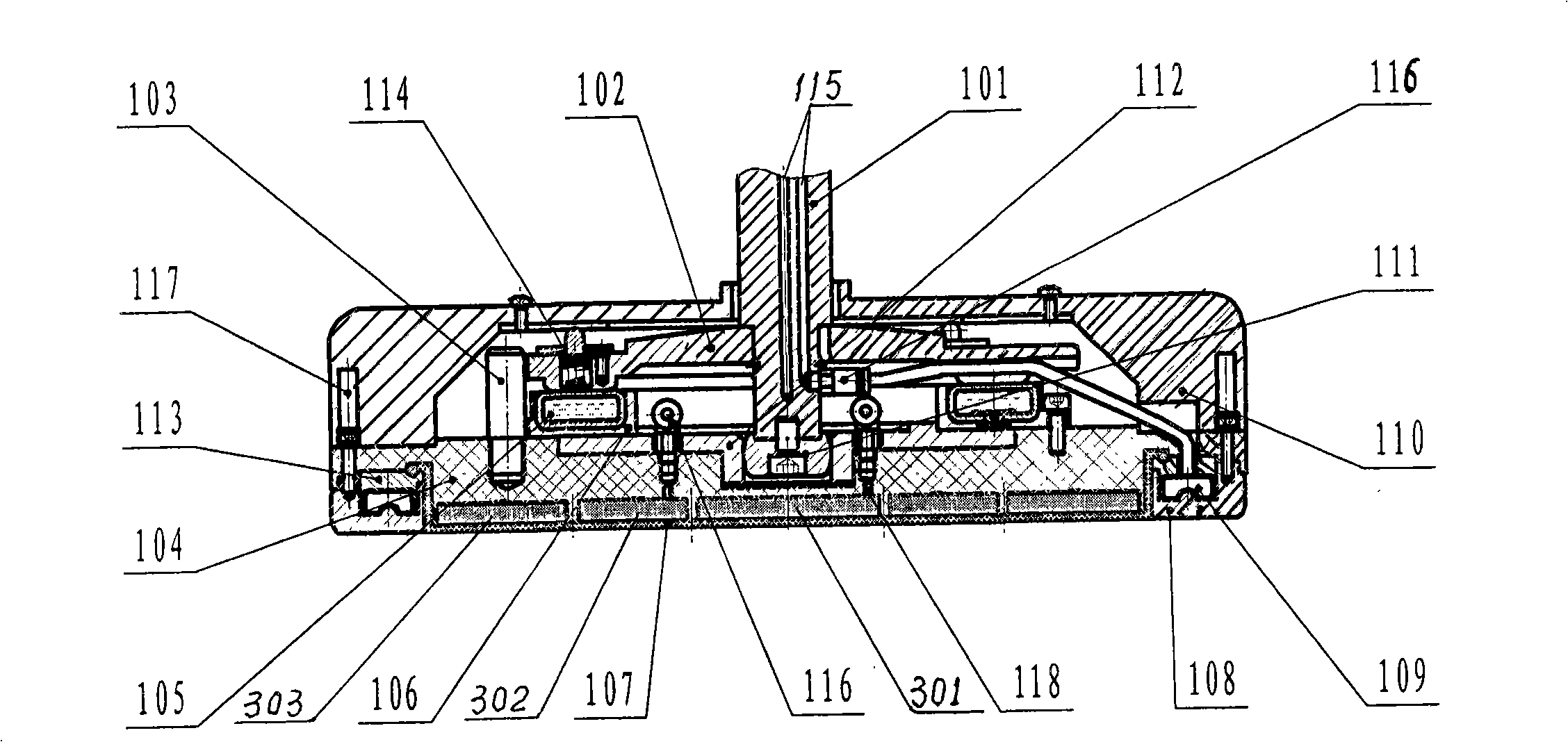
[0017] Referring to the accompanying drawings, the present invention includes a rotating shaft 101, and along the rotating shaft 101, an upper cover plate 110, a transmission plate 102, a base plate 104, a surrounding ring 108 and a back film 107 are arranged successively from top to bottom. The transmission shaft 101 is fixed, the upper cover plate 110 is fixed to the base plate 104, and the spring ejector pin 114 is installed on the drive plate 102. 104 is provided with drive pin 103, and back film 107 sticks on the lower surface of base plate 104, and its circumference is provided with fixing ring 113 and base plate 104 are fixed, surrounds holding ring 108 and has three or more than three evenly distributed along the circumference. The suspension rod is matched with the suspension hole provided by the base plate 104, and the spring plunger 117 corre...


PUM


Abstract

The present invention relates to a polishing head which is used in a chemical mechanical polishing device of a semiconductor wafer. The polishing head comprises a rotating shaft, and an upper cover plate, a driving disc, a base disc, a retaining ring and a back membrane which are orderly arranged along the rotating shaft from the top to the bottom. The driving disc is fixed on a transmission shaft. The upper cover plate is fixed on the base disc and is equipped with a spring top pin. The top of the spring top pin is contacted with the inner upper surface of the upper cover plate. A drive pin is arranged between the driving disc and the base disc. The back membrane is stunk on the lower surface of the base disc, and the surrounding edge of the back membrane is provided with a fixing ring which is fixed on the base disc. The retaining ring is hung at the base disc. A movable balance joint device is arranged between the driving disc and the base disc. The polishing head has good polishing quality and high polishing planeness.

Description

technical field [0001] The invention relates to a polishing head, in particular to a polishing head used on chemical mechanical polishing equipment for semiconductor wafers. Background technique [0002] Chemical mechanical polishing (CMP) is a method of planarizing or polishing a substrate of semiconductor material or other types of material. With the development of ultra-large-scale integrated circuits, the diameter of semiconductor wafers increases, while the size of circuit components decreases, resulting in a gradual decrease in the volume of components, resulting in a three-dimensional circuit structure, resulting in a sharp increase in the input and output leads of the chip. , The internal wiring and wiring density of the chip increase rapidly, and the cross-sectional area of ​​the wiring gradually decreases. With the increase of the number of metal layers, lithography requires that the surface of each layer must be flat. Chemical mechanical polishing is currently th...

Claims


Application Information

Patent Timeline
Patent Type & Authority Applications(China)
IPC IPC(8): B24B41/047H01L21/304
Inventor 种宝春柳滨周国安
Owner THE 45TH RES INST OF CETC
Learn More