
Measuring apparatus for reflection index of wave suction material

A technology of wave absorbing material and measuring device, which is applied in the field of microwave and millimeter wave testing, can solve the problems that affect the measuring accuracy of reflectivity of wave absorbing material, the machining accuracy of radius consistency is low, and the space occupied by the arcuate track is large.

Inactive Publication Date: 2009-01-14
UNIV OF ELECTRONICS SCI & TECH OF CHINA
View PDF0 Cites 30 Cited by
  • Summary
  • Abstract
  • Description
  • Claims
  • Application Information

AI Technical Summary

Problems solved by technology

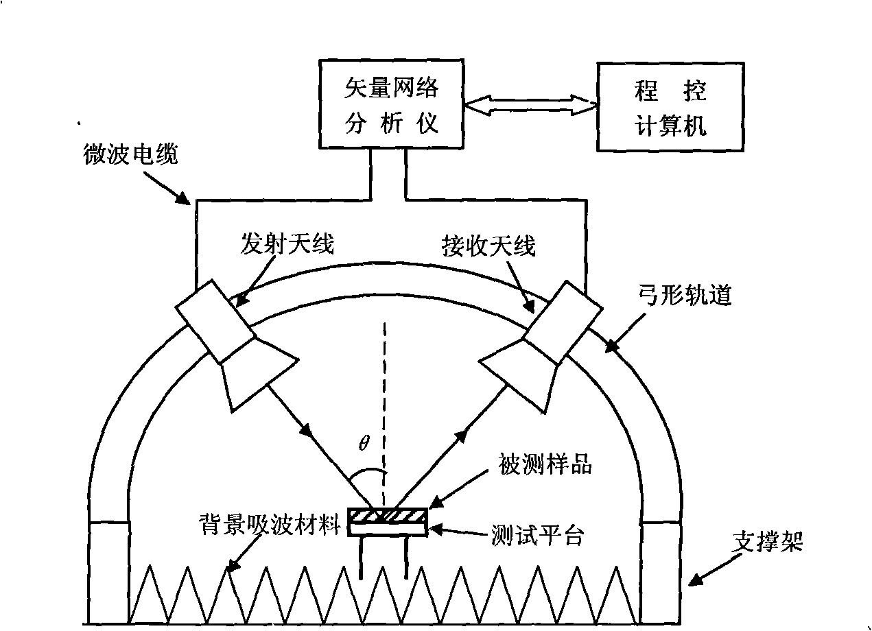
In the process of using the bow method to measure the reflectivity of the absorbing material, due to the poor accuracy of the radius consistency of the bow track and the positioning angle of the antenna, this directly affects the measurement accuracy of the reflectance of the absorbing material
Moreover, the large volume of the bow-shaped track will introduce certain scattering, which will also have a certain impact on the measurement accuracy and measurement range; at the same time, the bow-shaped track occupies a large space, which brings great inconvenience to the moving and storage of the test system
[0014] To sum up, the bow method is usually used at home and abroad to measure the reflectivity of absorbing materials under different incident angles, but the bow track has low processing accuracy due to the consistency of the radius during production, and will introduce certain scattering problems, so that Limits the further improvement of the reflectivity measurement accuracy of absorbing materials under different incident angles

Method used


Image

  • Measuring apparatus for reflection index of wave suction material
  • Measuring apparatus for reflection index of wave suction material
  • Measuring apparatus for reflection index of wave suction material

Examples


Embodiment Construction

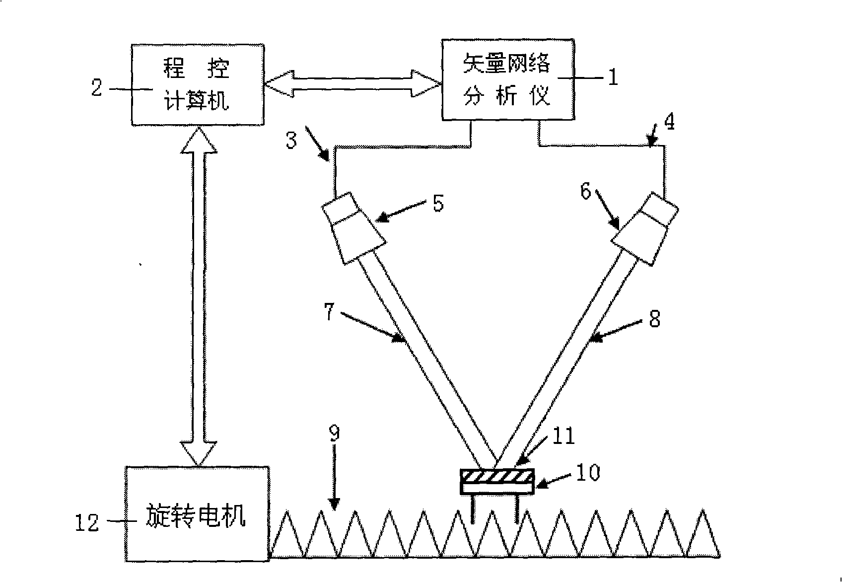
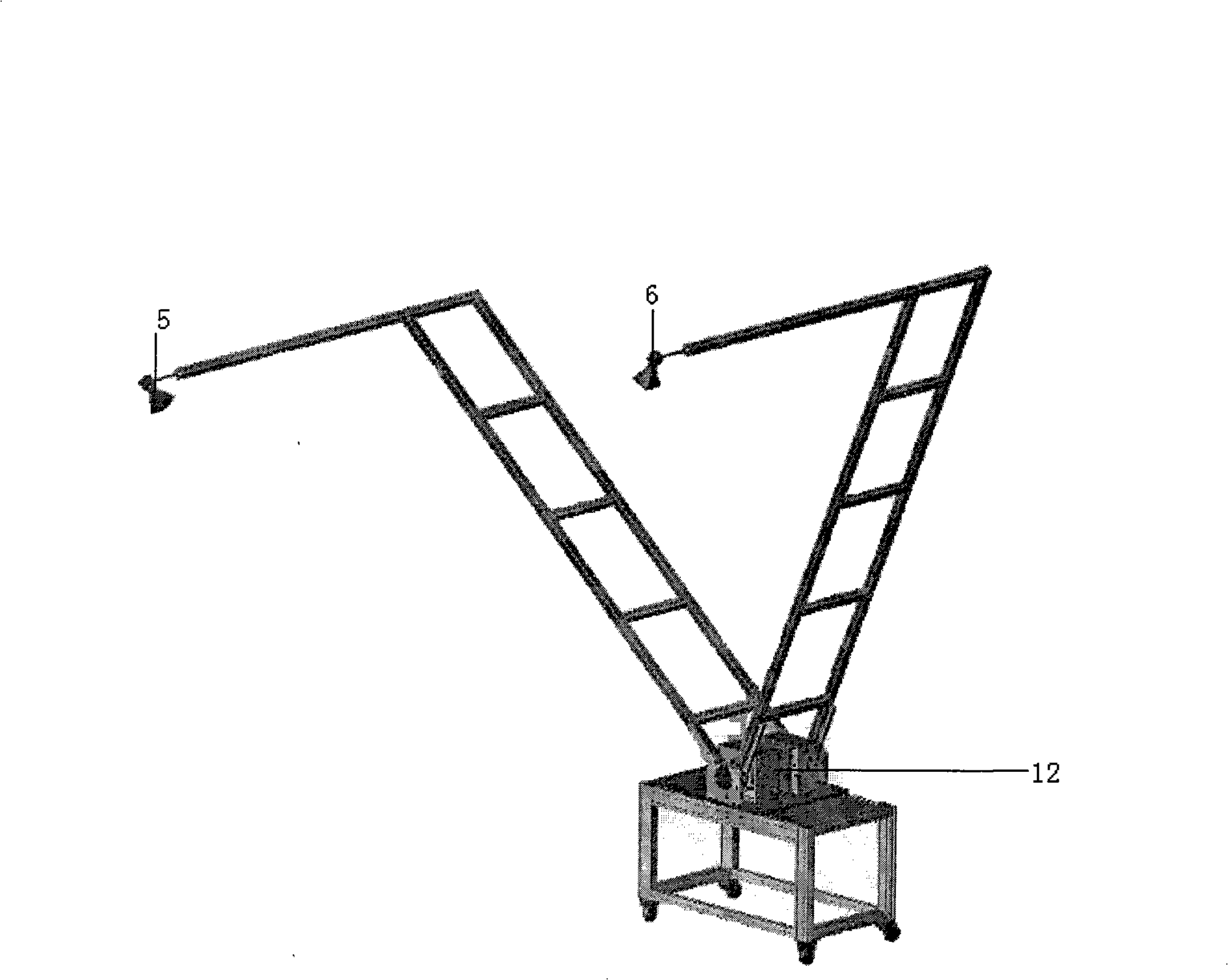
[0028] A device for measuring the reflectivity of absorbing materials, such as figure 2 , image 3 As shown, it includes a vector network analyzer 1, a program-controlled computer 2, a first microwave cable 3, a second microwave cable 4, a transmitting antenna 5, a receiving antenna 6, a first arm 7, a second arm 8, and a background absorbing material 9. Test platform 10, rotating motor 12. The vector network analyzer 1 and the program-controlled computer 2 are connected through a GPIB card, the vector network analyzer 1 and the transmitting antenna 5 are connected through the first microwave cable 3, and the vector network analyzer 1 and the receiving antenna 6 are connected through the first microwave cable. The two microwave cables 4 are connected, and the background absorbing material 9 is located under the test platform 10 .

[0029] Both the first arm 7 and the second arm 8 are in the shape of a "7", have the same size and structure, and are composed of a straight arm...


PUM


Abstract

The invention belongs to the technical field of microwave and millimeter wave testing, relates to the reflectivity testing of wave absorptive materials of microwave and millimeter wave, and provides a testing device that measures the reflectivity of the wave absorptive materials according to an arc method. Compared with existing reflectivity testing devices of the wave absorptive materials with arc methods, the invention provides an arc rail that consists of a first ally arm (7) shaped like a character '7' and a second ally arm (8) and can rotate around a rotating shaft of an electric rotating motor (12). When utilized in the reflectivity measurement of different incident angles, the testing device has ultra-convenient angle control and fixed radiuses of the ally arms, and can reduce the testing error that is caused by radius change. After adopting the structure that is shaped like the character '7', the testing device has reduced volume, and consequently can effectively reduce the disperse emission that is caused by an antenna fixing frame, raises measuring precision, and is convenient for loading, unloading, transportation and storage.

Description

technical field [0001] The invention belongs to the technical field of microwave and millimeter wave testing, and relates to the reflectivity testing technology of microwave and millimeter wave absorbing materials. Background technique [0002] Absorbing materials are widely used in military and civilian fields. With the rapid development of stealth technology, the requirements for the absorbing performance of absorbing materials are getting higher and higher. Reflectivity is an important index parameter used to characterize the absorbing performance of absorbing materials. Under a given wavelength and polarization condition, the measured high loss can be obtained by measuring the ratio of the reflected power of the electromagnetic wave from the same direction and the same power density to the mirror direction of the sample sample to be tested and the good conductor plane of the same size. The reflectivity of the material, see formula (1). [0003] Γ ...

Claims


Application Information

Patent Timeline
Patent Type & Authority Applications(China)
IPC IPC(8): G01N22/00
Inventor 郭高凤李恩罗明直张其劭周杨苏胜浩李宏福
Owner UNIV OF ELECTRONICS SCI & TECH OF CHINA
Learn More