Horizontal type electric dust collector

An electrostatic precipitator, horizontal technology, applied in the field of flue gas purification and dust removal devices, can solve problems such as difficulty in grasping the strength of the folded plate, low discharge efficiency at the outlet end, and material blockage, so as to ensure long-term effective operation and up-to-standard discharge , to ensure the effect of dust removal effect

Active Publication Date: 2009-01-21
JIANGSU KEHANG ENVIRONMENT ENG TECH
View PDF0 Cites 18 Cited by
  • Summary
  • Abstract
  • Description
  • Claims
  • Application Information

AI Technical Summary

Problems solved by technology

After testing and calculation, this part of side channeling air will affect the emission efficiency of the dust collector by about 0.01-0.02%.
In addition, the cathode rapping device of the existing electrostatic precipitator usually adopts the cleaning method of top drive side rotary rapping. The casing is connected to the inner cavity of the dust collector, and the airflow and temperature fluctuate greatly. The electromagnetic shaft is prone to condensation and dust accumulation and creepage, which will affect the service life of the electromagnetic shaft and the dust removal effect, and reduce work efficiency.
Furthermore, the expansion buffer connection device at the lower end of the dust hopper of the electrostatic precipitator is usu

Method used


Image

  • Horizontal type electric dust collector
  • Horizontal type electric dust collector
  • Horizontal type electric dust collector

Examples


Embodiment Construction

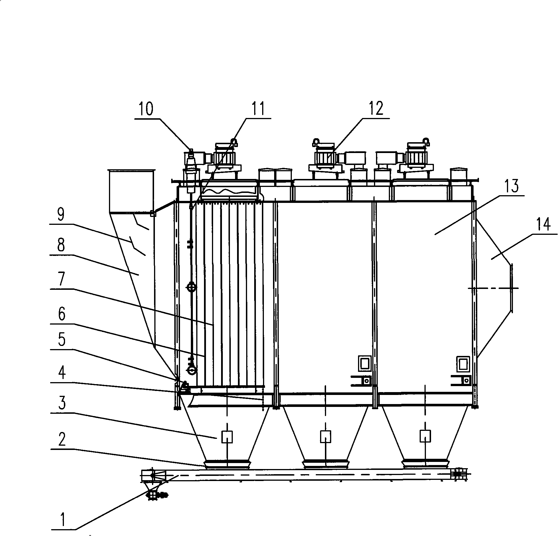
[0020] Below in conjunction with accompanying drawing and embodiment the present invention is described in further detail:

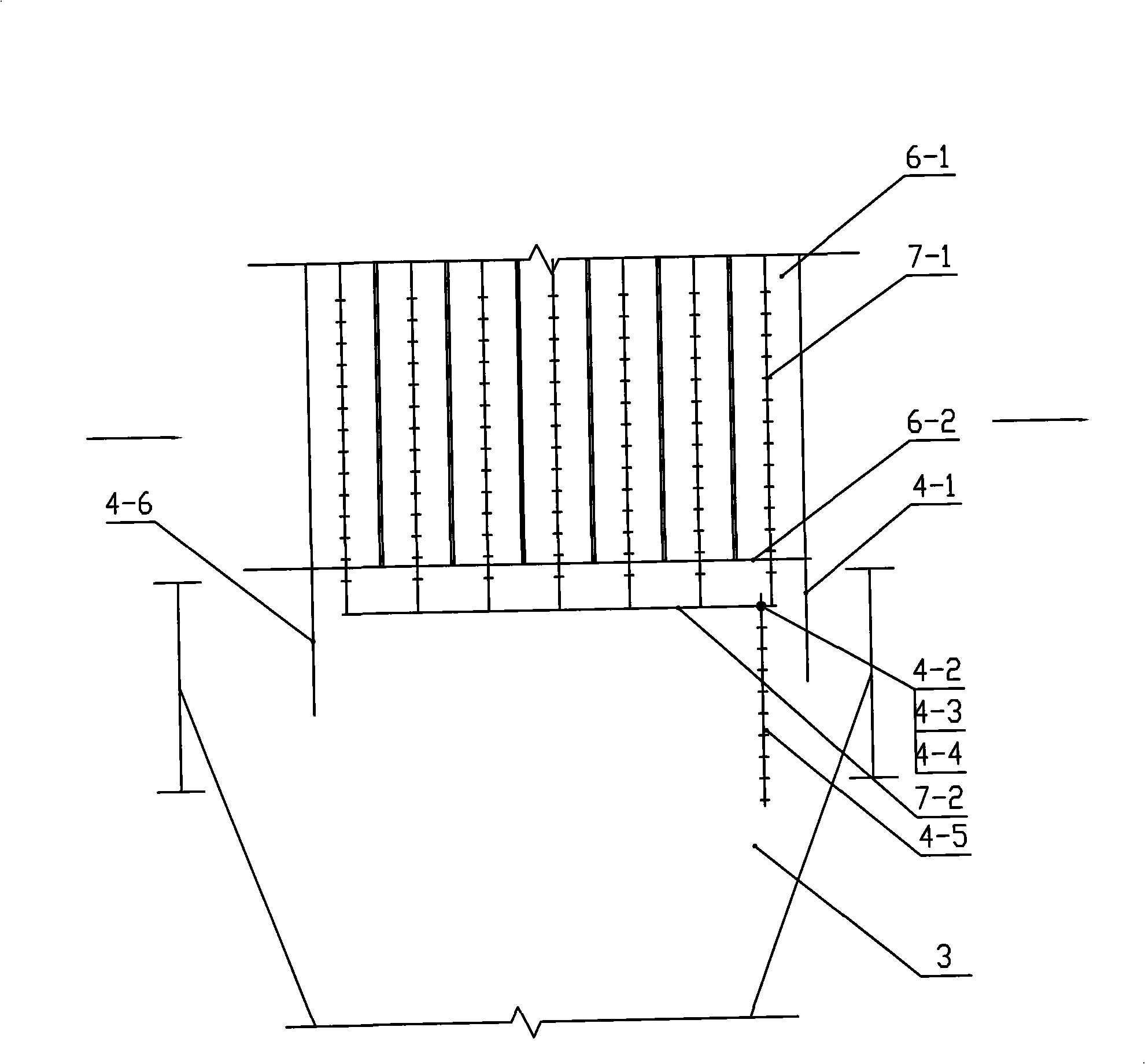
[0021]The present invention mainly consists of a casing 13, an inlet head 8, an outlet head 14, an ash hopper 3, an anode system 6, a cathode system 7, an anode rapping device 5, a cathode rapping device 11, a high voltage power supply 12 and an ash discharge device 1 Composition; the shell 13 is a closed filter chamber, and its front and rear ends are respectively provided with an inlet head 8 and an outlet head 14, and an airflow distribution device 9 is arranged in the inlet head 8. The lower end of the housing 13 is connected with the ash hopper 3, and the lower end of the ash hopper 3 is connected to the ash discharge device 1 through the expansion buffer device 2 of the discharge port; the cathode system 7 includes the cathode suspension beam, the cathode line 7-1 and the cathode The bottom beam 7-2, the upper and lower ends of several cathode wire...


PUM


Abstract

The invention provides a horizontal electric dust remover. A sealing head and an outlet sealing head are respectively arranged at the front and the back ends of a shell body, a dust hopper is connected at the lower end, a discharge outlet at the lower end of the dust hopper is connected with a dust discharge device by an expansion buffer device of the discharge outlet which is difficult to be blocked; a high voltage power supply is connected with a cathode system, an anode system and the cathode system are suspended in the shell body to form an electric field, the anode system carries out the dust removal by an anode vibration device, the cathode system carries out the dust removal by a cathode vibration device; a front air baffle, a back air baffle and a discharge lever are arranged in the dust hopper to constitute an air running and purifying device of the dust hopper. A heater is arranged in a cover shell of the cathode vibration transmission device, and an air suction pipe which is communicated with interior and exterior is arranged on the cover shell. The horizontal electric dust remover can overcome the shortcoming of the air running in a bypass of the dust hopper of the existing electric dust remover, avoid the problems of easy dewing and dust accumulation creepage of an electromagnetic rotary shaft in the cathode transmission device, prevent the occurrence of the phenomenon of dust accumulation blockage, effectively ensure the dust removing effect of the electric dust remover and ensure the emission to achieve the standards.

Description

technical field [0001] The invention relates to a flue gas purification and dust removal device, in particular to a horizontal electric dust collector. Background technique [0002] At present, electrostatic precipitators are widely used in flue gas purification and dust removal in electric power, cement and other industries. The existing horizontal electrostatic precipitator is mainly composed of shell, inlet head, outlet head, anode system, cathode system, anode rapping device, cathode rapping device, high voltage power supply, ash discharge device and so on. When working, a high-voltage direct current is delivered to the cathode system through a high-voltage power supply. Using the different geometric shapes of the cathode system and the anode system, a strong non-uniform electric field is generated between the electrodes to ionize the surrounding gas and generate a large number of electrons and positive and negative ions. When the dust-containing gas enters the electric...

Claims


Application Information

Patent Timeline
IPC IPC(8): B03C3/04B03C3/34B03C3/74
Inventor 刘怀平何美华徐志海
Owner JIANGSU KEHANG ENVIRONMENT ENG TECH
Why Eureka
Try Eureka