Method for rapid cooling of a hot isostatic press and a hot isostatic press

A hot isostatic press, rapid cooling technology, applied in the press, material forming press, heat transfer modification and other directions, can solve the problems of different cooling rates, sudden cooling, complex structure, etc., to achieve uniform temperature distribution Effect

Active Publication Date: 2009-01-21
克莱默热处理设备公司 +1
View PDF2 Cites 11 Cited by
  • Summary
  • Abstract
  • Description
  • Claims
  • Application Information

AI Technical Summary

Problems solved by technology

The disadvantage of this embodiment is that the very cold fluid flows back from below into the high-temperature zone and comes into direct contact with the workpiece in the furnace, so that the low-temperature gas fills the high-temperature zone from bottom to top
Its disadvantage is that sudden cooling with too uncertain parameters may occur, and it is impossible to achieve a uniform cooling rate in the entire charge area
The conditions required by this method are complex, so it is also necessary to use a hot isostatic press with a complex structure and several pipes
If the undercut portion of the charge or the support structure of the charge prevents the normal circulation of the charge zone, the re-fed mixed fluid may flow back into the charge zone in an uncontrolled manner and sometimes cause different cooling rates, which is also a shortcoming
In addition, feeding the gas cooled to the mixed temperature into the charge area from below will inevitably lead to a temperature gradient between the lower end and the upper end of the charge area, so it is impossible to achieve a uniform cooling rate

Method used


Image

  • Method for rapid cooling of a hot isostatic press and a hot isostatic press
  • Method for rapid cooling of a hot isostatic press and a hot isostatic press
  • Method for rapid cooling of a hot isostatic press and a hot isostatic press

Examples


Embodiment Construction

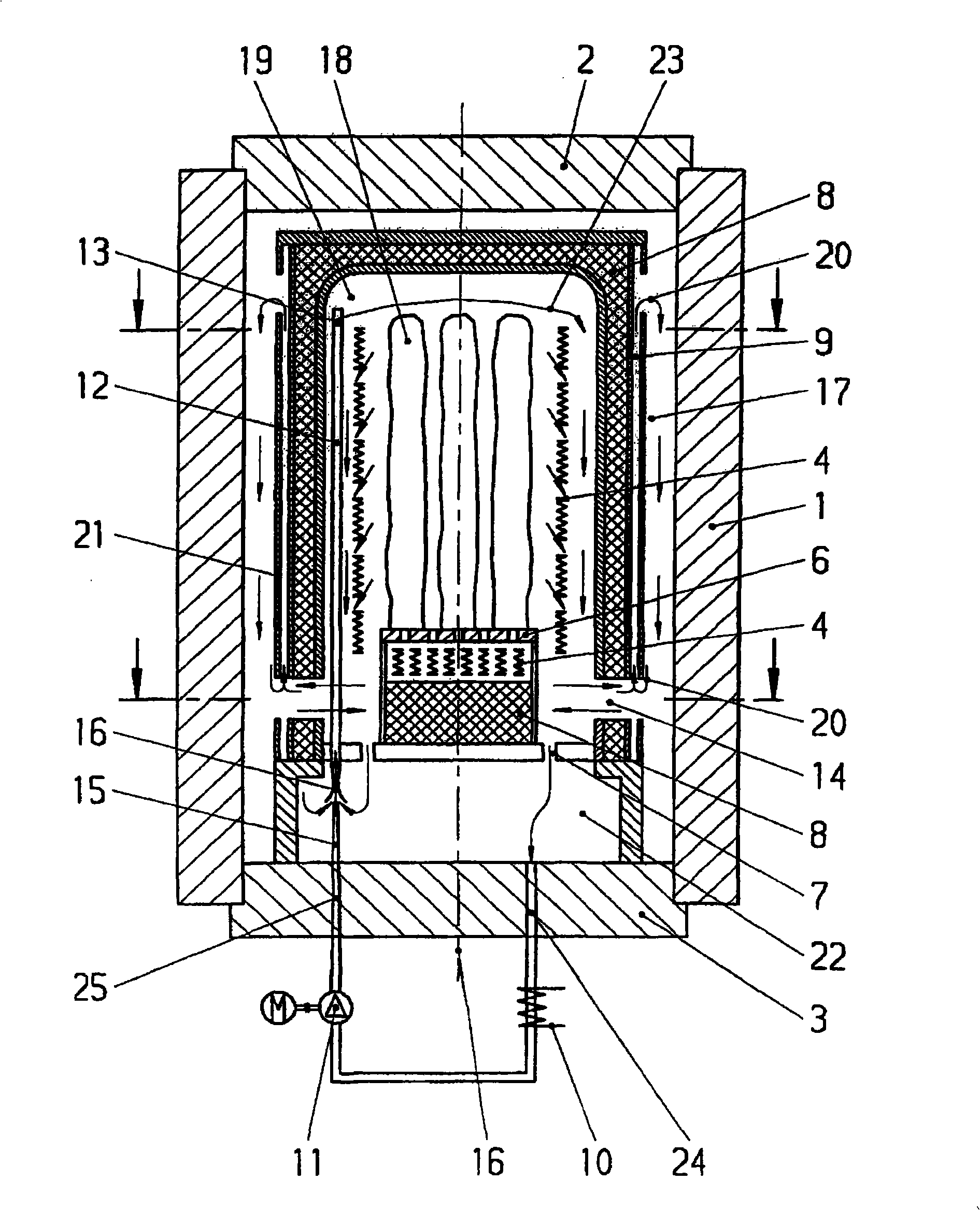
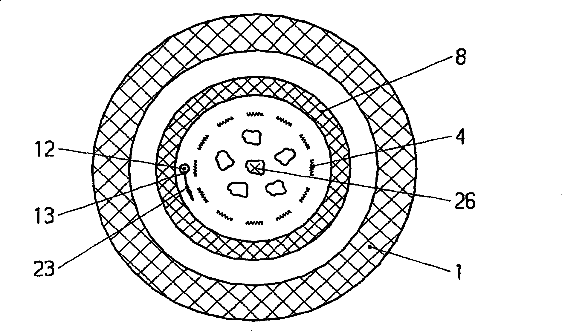
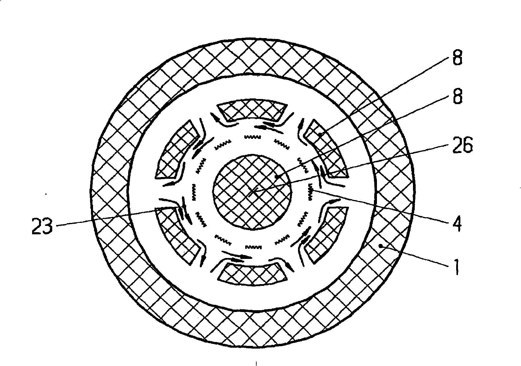
[0018] The pressure vessels 1 shown in these figures each have a generally inner charge zone 19 and a thermal insulation 8 arranged therebetween. The heating element 4 is installed in the insulating body 8, and the charge 18 is usually placed on a charge pallet 6, or it is placed on the charge pallet 6 by means of a bracket (not shown). The pressure vessel 1 also has closing caps 2 and 3 for filling and discharging the pressure vessel, but for the sake of simplicity of description, these are considered to be part of the pressure vessel 1 below. At least one nozzle 13 is installed in the charge area 19 within the area of ​​the heat insulating body 8 , through which a swirling flow 23 is formed, in particular a fluid is injected at high speed. The fluid has a lower temperature than the fluid in the charge zone 19 and / or the charge 18 and is brought into close contact with the inner wall of the insulator 8 by the action of rotation according to the laws of physics. When the swir...


PUM


Abstract

The present invention relates to a method for quickly cooling hot isostatic press which is formed by a pressure container (1). The inner part of the pressure container is provided with a furnace material area (19) and an insulator (8) arranged therein. A heating element (4) is provided in the range of the insulator (8), and the furnace material (18) is arranged on the furnace material splint (6). The method is characterized in that fluid is injected into the inner part of the furnace material area (19) of the pressure container (1) through at least one nozzle (13) to form a rotational flow (23). The fluid is blended with the fluid adjacent with the furnace material (18) in the flowing process of the rotational flow (23) by the insulator (8), and furthermore the temperature of fluid flowing out of the nozzle (13) is lower than that of the fluid in the furnace material area (19) or the furnace material (18). In the hot isostatic press commended by the invention, at least one pipe (12) in the pressure container (1) is connected with at least one nozzle (13) in the furnace material area (19) and provides cryogenic fluid to the pipe (12).

Description

technical field [0001] The invention relates to a rapid cooling method of a hot isostatic press and a hot isostatic press. Background technique [0002] Hot isostatic presses (HIP) or autoclaves are used in a wide variety of applications today. Under high temperature and high pressure conditions, the solid workpiece or the molding material composed of powder is densified in the mold. It is possible to combine materials of the same type as well as different materials. Typically the workpiece is placed in a furnace surrounded by a high pressure vessel. During or after heating, a fluid or inert gas (usually argon) is used to apply pressure from all directions, and a thorough isostatic pressing is performed until the workpiece reaches the optimum density. This method is also used to re-densify components, such as components made of ceramic materials, for example for hip prostheses, aluminum castings for automobile or engine construction, cylinder heads for car engines or tita...

Claims


Application Information

Patent Timeline
IPC IPC(8): B22F3/15
CPCB30B11/002B22F3/15F28C3/02F28F13/02B22F2003/153
Inventor M·格拉夫
Owner 克莱默热处理设备公司
Why Eureka
Try Eureka