
Numerical control reverse direction machining aggregate machinery

A technology of combined machine tools and fixtures, applied in metal processing machinery parts, metal processing, metal processing equipment, etc., can solve the problems of large area of ​​​​the automatic line of combined machine tools, inability to convert production models, and high investment costs, saving auxiliary The effect of time, uniform force and improved processing efficiency

Inactive Publication Date: 2009-01-21
JIANGSU HENGLI MACHINE TOOL
View PDF0 Cites 8 Cited by
  • Summary
  • Abstract
  • Description
  • Claims
  • Application Information

AI Technical Summary

Problems solved by technology

[0003] The automatic line of combined machine tool is composed of several machine tools. The workpiece is positioned and clamped by the fixture through the conveying device. The tool is installed on the multi-spindle box. The multi-spindle box is driven by the feed slide table for cutting. It is suitable for a single variety. For the processing of mass-produced parts, the automatic line of combined machine tools occupies a relatively large area, the one-time investment cost is high, the time is long, the effect is slow, and the conversion of production and model cannot be realized, and the risk is high

Method used


Image

  • Numerical control reverse direction machining aggregate machinery

Examples


Embodiment Construction

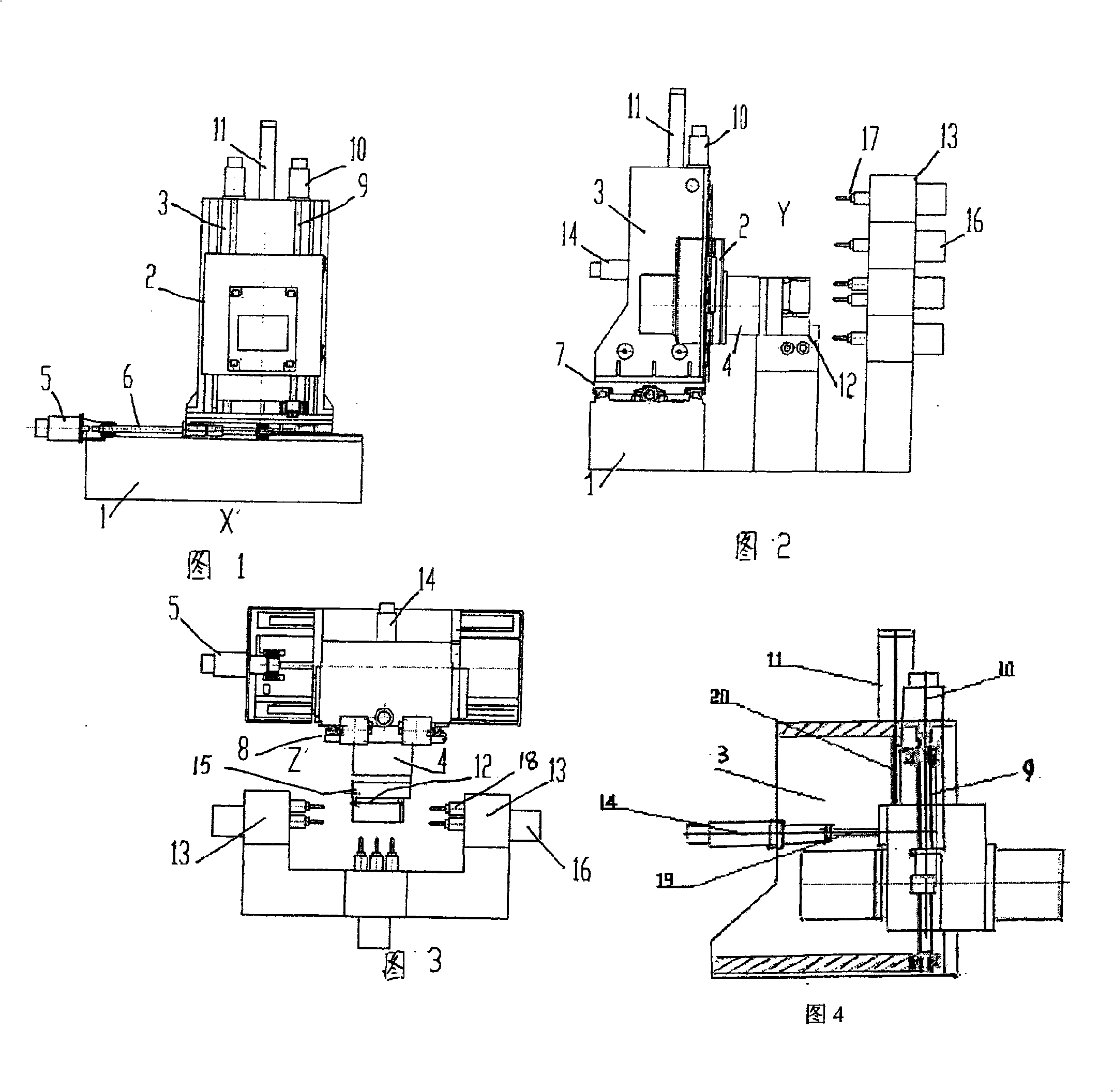
[0032] Embodiment of the present invention: the column 3 and the base 1 are provided with an X-axis guide rail 7, the column 3 is provided on the base 1, driven by the X-axis servo motor 5, driven by the X-axis ball screw 6, and moves along the X-axis guide rail 7 ; The slide plate 2 and the column 3 are provided with a Y-axis guide rail 8, the slide plate 2 is arranged on the column 3, and two Y-axis servo motors 10 are driven at the same time, driven by the Y-axis ball screw 9, moving along the Y-axis guide rail 8, and on the column 3) A hydraulic balance oil cylinder 11 is installed at the center position of the top, and one end of the piston rod 20 is connected with the slide plate 2; the slide plate 2 and the ram 4 are provided with a Z-axis guide rail 14, the ram 4 is provided on the slide plate 2, and the Z-axis servo motor 14 The drive is driven by the Z-axis ball screw and moves along the Z-axis guide rail 14; the tooling fixture 12 can be set on the B-axis rotary shaf...


PUM


Abstract

The invention relates to a numerical control reverse processing combined machine tool which is composed of a work fixture unit for fixing a part to be processed, a motor, an X axis direction guide way, a Y axis direction guide way, a Z axis direction guide way, a spindle box module for fixing tools, a sliding plate, a ram, an upright post and a base; the upright post and the base are provided with the X axis direction guide way, and the upright post is arranged on the base and can move along the X axis direction guide way; the upright post is provided with the Y axis direction guide way, and the sliding plate is arranged on the upright post and can move along the Y axis direction guide way; the sliding plate and the ram are provided with the Z axis direction guide way, and the ram is arranged on the sliding plate and can move along the Z axis direction guide way; the work fixture can be arranged on a revolving axle of a B axis; the upright post does horizontal linear movement oppositely to the base along the X axis direction; the sliding plate does vertical linear movement oppositely to the upright post along the Y axis direction; the sliding plate is arranged along the Z axis direction and internally provided with the ram, and square holes on the sliding plate and the ram longitudinally stretch back and forth to form the longitudinal and horizontal movement of the Z axis; the work fixture can be directly installed on the end face of the ram of the Z axis, or placed on the revolving axle of the B axis and then mounted on the end face of the ram, and the tool is installed on the spindle of a multi-spindle box.

Description

technical field [0001] The invention relates to the structure of a numerically controlled combination machine tool. Background technique [0002] The CNC reverse machining module combination machine tool is a kind of tooling fixture that can move in the X-axis direction, Y-axis direction, and Z-axis direction (or Y-axis direction and Z-axis direction), and several multi-spindle box modules are fixed. A new type of reverse machine tool. In the CNC reverse processing module combination machine tool, the X-axis direction is the horizontal linear movement of the column relative to the base; the Y-axis direction is the vertical linear movement of the slide plate relative to the column; the Z-axis direction is the slide plate is equipped with a ram, the square hole between the ram and the slide plate The front and rear longitudinal expansion and contraction constitute the longitudinal and horizontal movement of the Z axis. Install a tooling fixture (or a tooling fixture with B-a...

Claims


Application Information

Patent Timeline
IPC IPC(8): B23Q39/00B23Q1/01B23Q1/26
Inventor 仲秋许兴旺蔡国保
Owner JIANGSU HENGLI MACHINE TOOL
Learn More