Elevator safety device and control method thereof

An elevator safety device and elevator control technology, which is applied in transportation, packaging, elevators, etc., can solve the problems of threatening life safety and prone to personal injury and death, and achieve the effect of low cost and easy realization

Active Publication Date: 2009-01-21
HITACHI ELEVATOR CHINA
View PDF0 Cites 8 Cited by
  • Summary
  • Abstract
  • Description
  • Claims
  • Application Information

AI Technical Summary

Problems solved by technology

[0003] However, due to various reasons, individual elevators may have an abnormal situation where the hall door lock switch is short-circuited and not removed. Before the maintenance personnel have completely exited the door area, the elevator suddenly enters the normal

Method used


Image

  • Elevator safety device and control method thereof
  • Elevator safety device and control method thereof
  • Elevator safety device and control method thereof

Examples


Embodiment 1

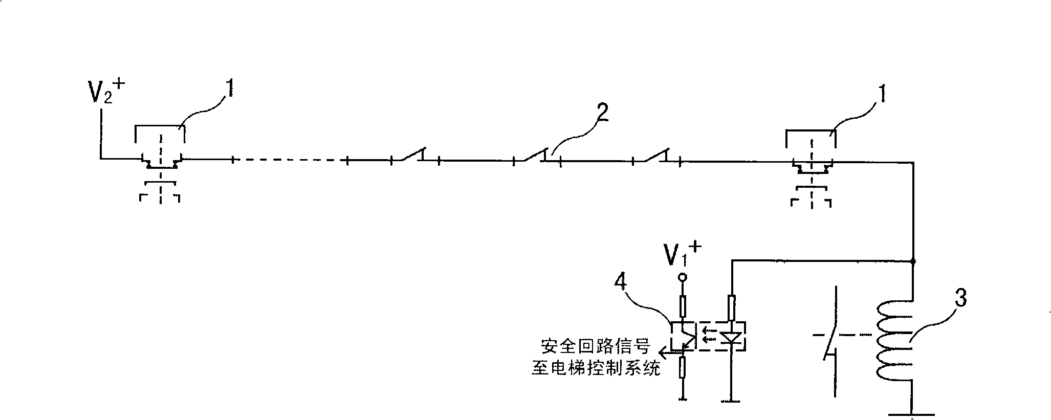
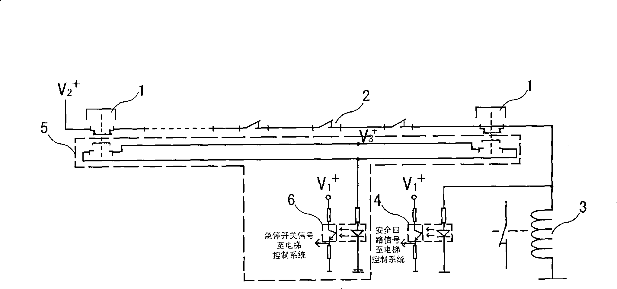
[0020] As shown in Figure 2(a), the present invention adds a detection circuit 5 to the original elevator system (MCU circuit or operation logic processing circuit system), and adopts the logical relationship of "or" to the emergency stop switch 1 in the hoistway It is connected to the I / O interface of the elevator control system, and the signal is sampled by the central processing unit. Wherein, the detection circuit 5 includes a photocoupler 6, the signal input end of the photocoupler is connected with the emergency stop switch, and the signal output end is connected with one of the I / O interfaces of the elevator control system for detecting the emergency stop switch. Restore signal.

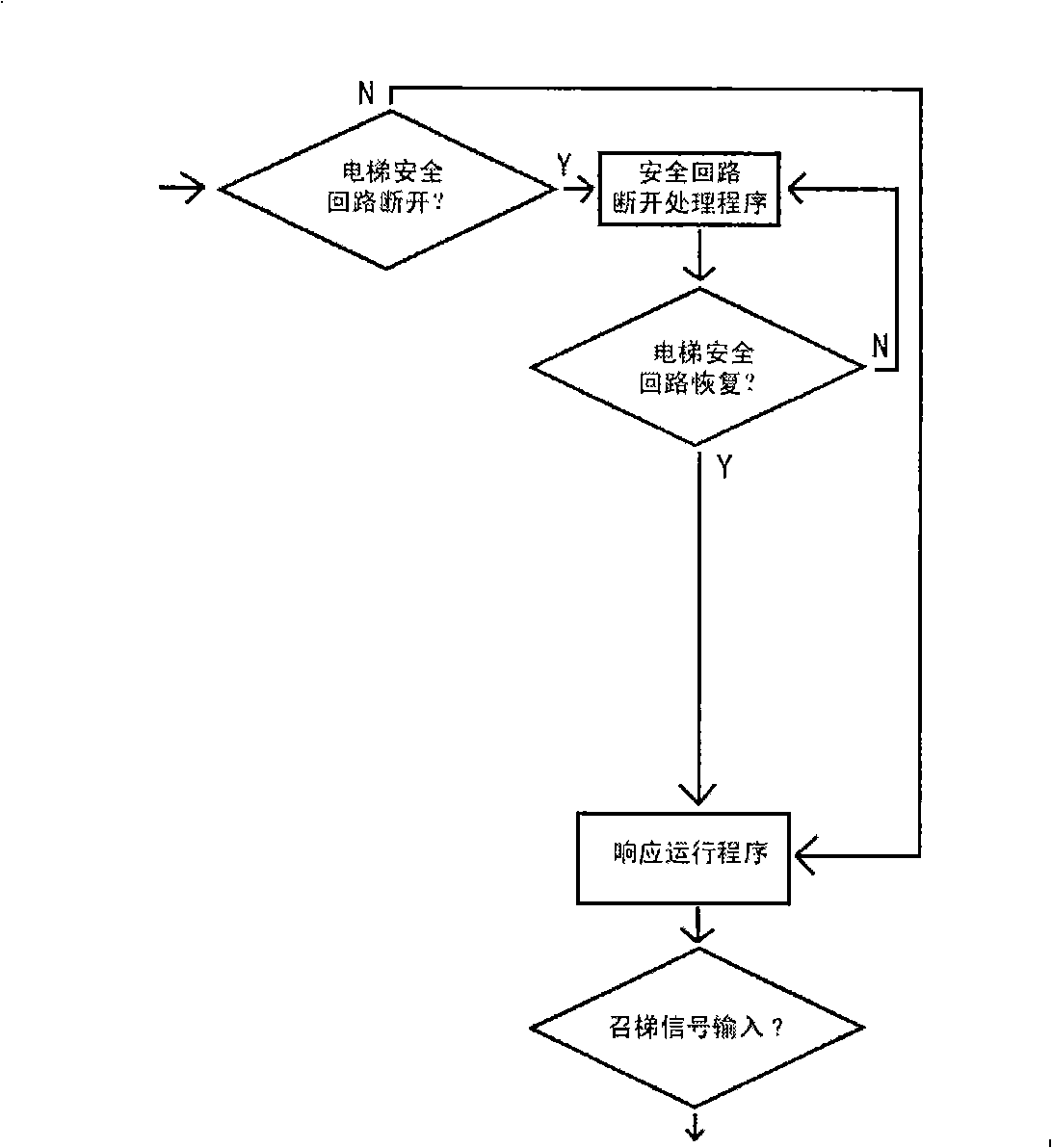
[0021] Shown in Fig. 2 (b) is the working flow chart of the present invention, in elevator operation process, at first detects whether elevator safety loop is disconnected, if not disconnected, then normal response elevator running program; If detect safety loop disconnection If the open sign...

Embodiment 2

[0023] Such as image 3 Shown is another embodiment of the present invention, this embodiment is in the safety circuit of existing elevator system, a plurality of emergency stop switches 1 in the elevator hoistway are formed into the logic relation of "or", and through delay relay The controlled normally closed contact 7 is connected in series to the safety circuit to realize the delayed recovery of the emergency stop switch. The loop shown in dotted line box 8 among the figure is similar to the time-delay program that detection loop 5 realizes in the first embodiment, need not increase the I / O loop of optocoupler and input central processing unit, also need not revise original control program, directly The delayed recovery of the emergency stop switch is realized by the control of the delay relay. The working process is also similar, both by delaying the recovery of the emergency stop switch to ensure that the maintenance personnel have sufficient time to exit the door area, ...


PUM


Abstract

The invention discloses a safety device for an elevator and a control method thereof. The safety device for the elevator comprises a safety loop consisting of an emergency stop switch, a safety sensor and a safe operation contactor which are connected serially, as well as a detection loop. The detection signal end of the detection loop is connected with the emergency stop switch, and is used for detecting the recovery signal of the emergency stop switch; and the signal output end of the detection loop is connected with an elevator control system, and is used for starting a time delay program when an effective recovery signal of the emergency stop switch is detected. The elevator safety control method is applied to the elevator control system in the safety recovery process of the emergency stop switch; and when the elevator control system detects the recovery signal of the emergency stop switch and judges the recovery signal to be effective, the time delay program is automatically called, so as to allow the emergency stop switch to recover after a certain period of time delay. The elevator safety device can effectively avoid personal safety accidents from occurring because the functions of an on-site door lock device are shielded and do not recover yet when elevator maintenance personnel withdraw from a door area after elevator shaft operation.

Description

technical field [0001] The invention relates to an elevator safety device, in particular to a device for improving the personal safety of maintenance personnel when the elevator hall door lock is short-circuited and not removed, and a control method for the safety device. Background technique [0002] When the elevator needs to be repaired or maintained, the maintenance personnel usually restore the emergency stop switch (usually a manually controlled push-type switch, connected in series to the control circuit of the equipment after entering the elevator shaft and completing the work, which is used for quick stop in emergency situations) Stop the equipment to avoid abnormal operation. The detailed principle will be further described in the following embodiments) and exit the hoistway. When the hall door is closed, the elevator can respond to the call or automatically return to the base station and enter the rated speed operation under normal conditions. . [0003] However,...

Claims


Application Information

Patent Timeline
IPC IPC(8): B66B5/00B66B1/00
Inventor 林汪金
Owner HITACHI ELEVATOR CHINA
Why Eureka
Try Eureka