Gear drive system of engine

A technology of gear transmission and engine, which is applied in the field of gear transmission system, can solve the problems of larger engine size, larger engine axial size, and lower reliability, and achieve improved reliability, simple and reliable positioning, and compact layout. Effect

Inactive Publication Date: 2009-01-21
WUXI KIPOR MACHINERY CO LTD
View PDF0 Cites 5 Cited by
  • Summary
  • Abstract
  • Description
  • Claims
  • Application Information

AI Technical Summary

Problems solved by technology

This structure only considers the requirements of engine transmission, but does not consider that doing so will in

Method used


Image

  • Gear drive system of engine
  • Gear drive system of engine
  • Gear drive system of engine

Examples


Example Embodiment

[0015] The present invention will be further described below in conjunction with the embodiments in the drawings:

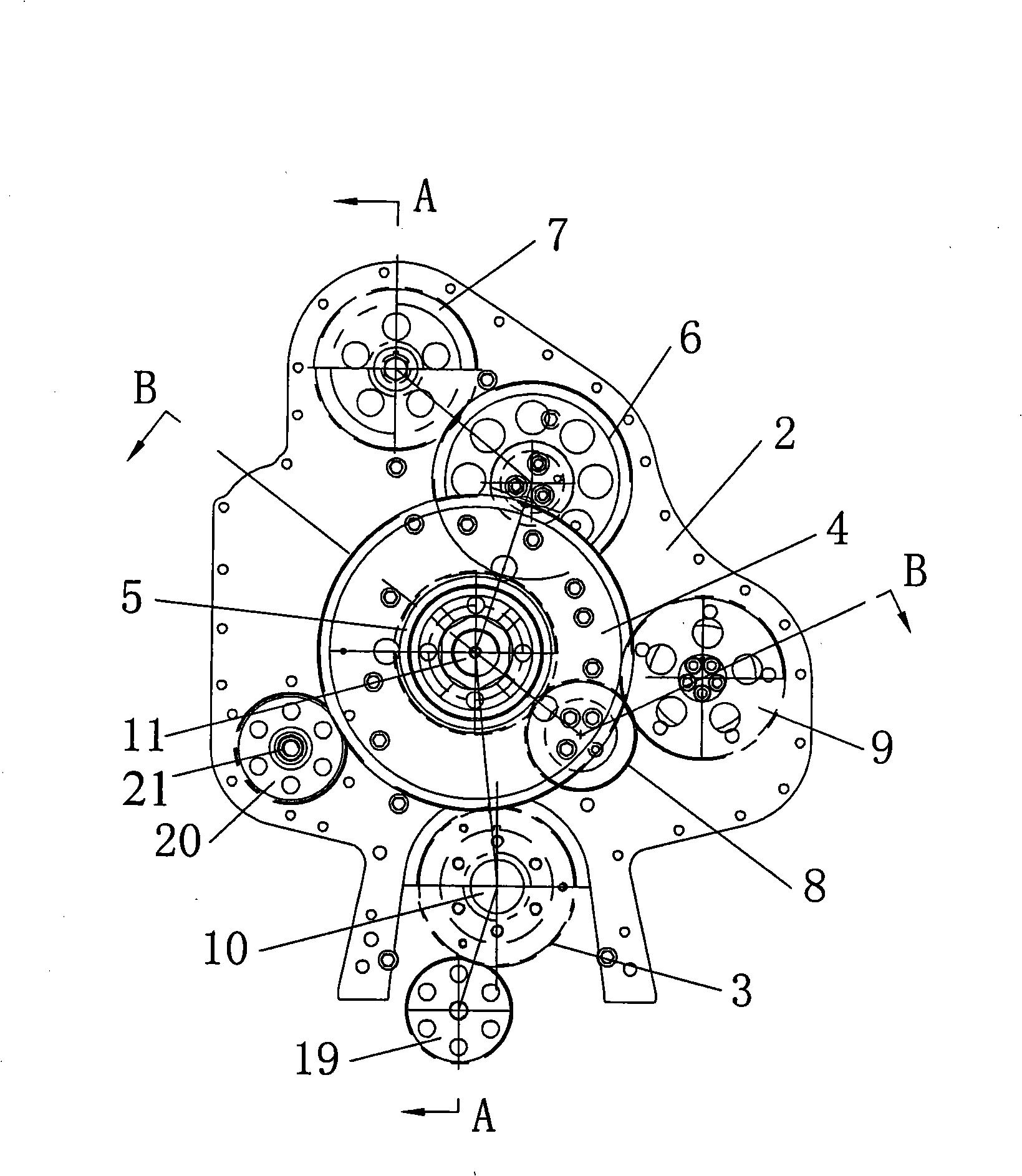
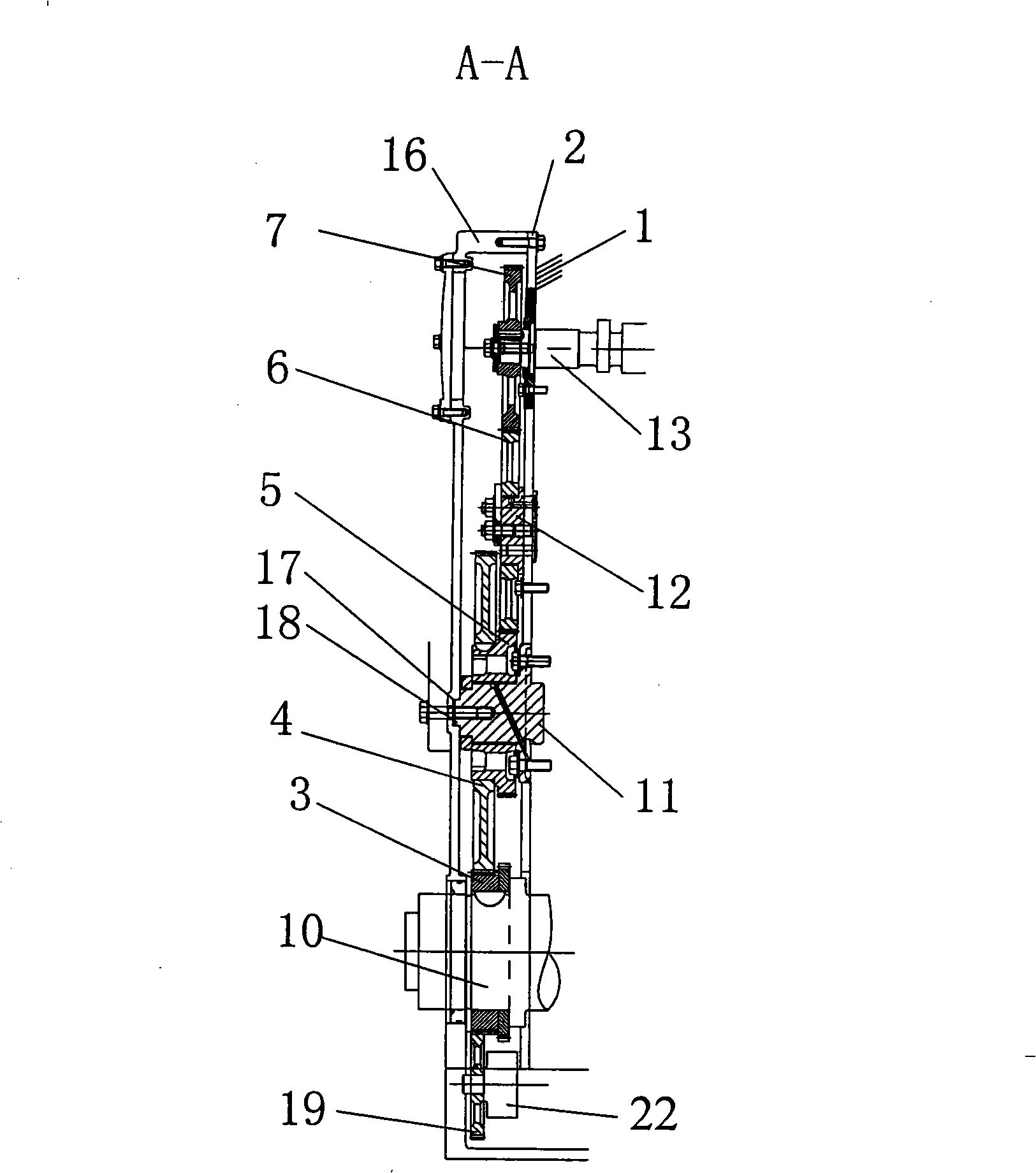
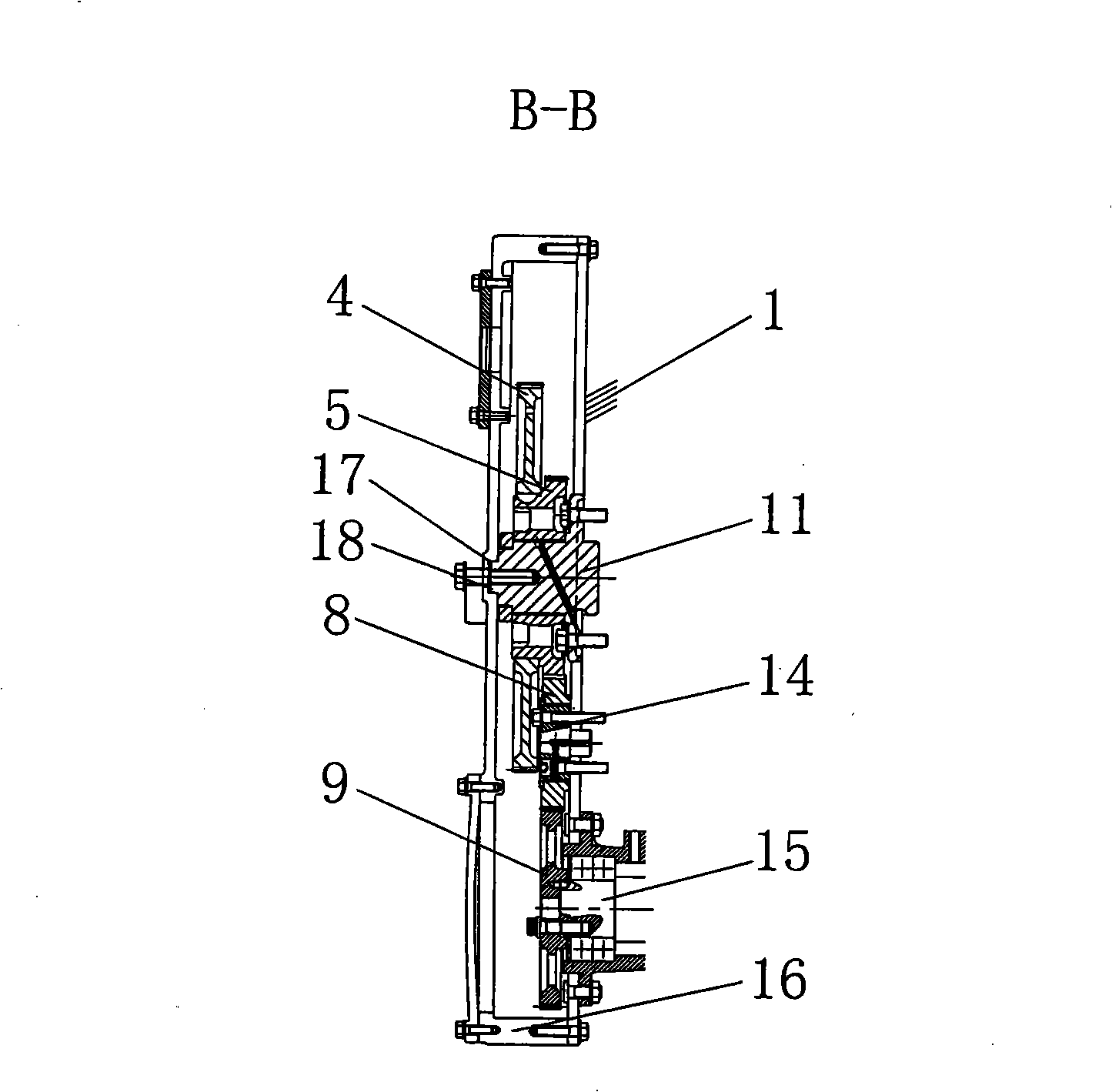
[0016] Figure 1 ~ Figure 3 As shown, it includes body 1, bottom plate 2, crankshaft timing gear 3, large gear 4, pinion gear 5, first idler gear 6, camshaft drive gear 7, second idler gear 8, fuel injection pump gear 9, crankshaft 10, Central shaft 11, first idler gear shaft 12, camshaft 13, second idler gear shaft 14, output shaft 15, gear chamber cover 16, recessed hole 17, shaft head 18, oil pump drive gear 19, water pump drive gear 20, Water pump drive shaft 21 and oil pump drive shaft 22.

[0017] Such as Figure 1 ~ Figure 3 As shown, the bottom plate 2 of the present invention is fixed on the front end surface of the engine body 1, the crankshaft 10 is installed in the body 1, the crankshaft timing gear 3 is installed on the crankshaft 10, and the central shaft 11 and the first idler are installed on the bottom plate 2 through bolts. Gear shaft 12, cam shaft 1...


PUM


Abstract

The invention relates to a pinion unit for engines, which is characterized in that a bottom plate is fixed on the engine body; a center shaft, a first idle gear shaft, a cam shaft, a second idle gear shaft, an output shaft, a driving shaft for a water pump and a driving shaft for an oil pump; a gearwheel and a pinion are coaxially arranged on the center shaft; the gearwheel is engaged with a crankshaft timing gear; a driving gear for the cam shaft is arranged on the cam shaft; a gear of the fuel injection pump is fixed on the output shaft; the gearwheel is engaged with a driving gear for the water pump; the driving gear for the water pump is arranged in a gear chamber and is arranged on the driving shaft for the water pump; the crankshaft timing gear is engaged with a driving gear for the oil pump; and the driving gear for the oil pump is arranged on the driving shaft for the oil pump. The pinion unit fully utilizes the space of the gear chamber, ensures that the axial size of the engine is utilized to the utmost extent, decreases the axial size of the whole engine, is more compact in arrangement, and simultaneously improves transmission reliability as well.

Description

technical field [0001] The invention relates to a gear transmission system of an engine, in particular to the arrangement of a water pump and an oil pump of the engine in a gear chamber, and belongs to the technical field of internal combustion engines. Background technique [0002] In the past, the water pump of the multi-cylinder engine was driven by the belt drive of the crankshaft pulley, and the oil pump was driven by the gear on the camshaft. This structure only considers the requirements of the engine transmission, but does not consider that doing so will increase the axial size of the engine, which will increase the overall size of the engine and reduce reliability. Contents of the invention [0003] The object of the present invention is to overcome the above disadvantages, so as to provide a gear transmission system of the engine which can reduce the axial size of the engine and further reduce the overall size of the engine. [0004] According to the technical s...

Claims


Application Information

Patent Timeline
IPC IPC(8): F02B67/04
Inventor 肖亨琳
Owner WUXI KIPOR MACHINERY CO LTD
Why Eureka
Try Eureka