Transmission shaft structure

A technology for transmission shafts and transmission parts, applied in the field of transmission shafts, can solve the problems of inability to locate in the middle position, slow actuation speed, difficult replacement of components and maintenance, etc., to reduce occupied space, ensure concentricity, and be easy to assemble Effect

Inactive Publication Date: 2009-01-21
MPI CORP
View PDF2 Cites 23 Cited by
  • Summary
  • Abstract
  • Description
  • Claims
  • Application Information

AI Technical Summary

Problems solved by technology

[0004] Comparing the above two existing structures, it can be known that the power output shaft and the screw rod of the drive motor can be connected by transmission elements such as belts, chains or gears (such as figure 1 structure shown), the screw can also be set coaxially with the motor power output shaft (such as figure 2 shown in the structure), it can also be seen on the market that threads are provided on the power output shaft of the motor to directly transmit power, appropriately reduce the volume and the space it occupies, but the aforementioned structures are all aimed at the relationship between the motor and the screw, and the screw and the slide rail are always Two independent components are set separately. Therefore, when adjusting the displacement accuracy of the platform, multiple sets of screws and slide rails must be adjusted at the same time, as well as components such as slide seats, sliders, and connecting seats that match the slide rails, especially the screws and slide rails. The parallelism of the rails is not easy to adjust, and it must consume a lot of labor and time, and because of the complex components, it not only takes up space, but also it is difficult to replace components and maintain
[0005] It must also be noted that, figure 2 The existing structure shown is to use a pneumatic cylinder to control the working platform 30 to move up and down the Z axis. Although this driving method is commonly used by the general industry, and the pneumatic cylinder can be replaced by an oil hydraulic cylinder, the air pressure or The disadvantage of hydraulic drive is that its actuation speed is slow, and the remote control often has the phenomenon of terminal pressure drop, and the oil pressure is prone to oil leakage due to the influence of ambient temperature, resulting in energy consumption. In addition, its main disadvantage is that it cannot be accurately controlled. Positioned in the middle position, therefore, for the stepless height adjustment device or equipment, the aforementioned method of cooperation between the screw and the slide rail must still be used

Method used


Image

  • Transmission shaft structure
  • Transmission shaft structure
  • Transmission shaft structure

Examples


Embodiment Construction

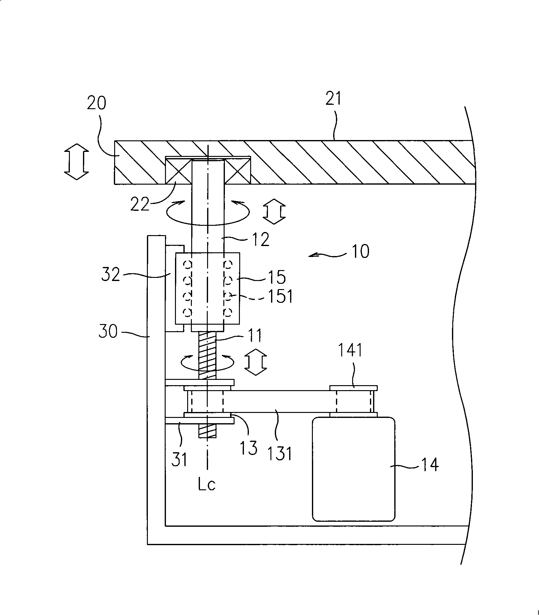
[0034] see image 3 As shown, the transmission shaft structure 10 proposed by the present invention mainly includes a screw rod 11 and a slider 12, the screw rod 11 is arranged in a vertical direction, and the slider 12 is integrally formed on the coaxial line Lc The top of the screw 11 and the top of the slider 12 are pivotally connected to a platform 20, the platform 20 has a bearing surface 21 for carrying objects, the screw 11, the slider 12 The axis Lc is perpendicular to the bearing surface 21, that is, the bearing surface 21 is set horizontally; secondly, a ball nut 13 is screwed outside the screw rod 11, and the ball nut 13 It is positioned on the machine platform 30 by the positioning piece 31, and is connected with the power output shaft 141 of a driving motor 14 through a belt 131. As is well known to those skilled in the art, the belt 131 can also be a chain or other Transmission parts with the same transmission function.

[0035] When the drive motor 14 rotates,...


PUM


Abstract

The invention is a driving shaft structure, which comprises a screw bolt and a sliding piece which is coaxially arranged with the screw bolt, the sliding piece is penetrated in a sleeve piece, the screw bolt is rotated by driving of a motor, can perform linear displacement which is parallel to the axial direction of the screw bolt, and can synchronously drive the sliding piece to rotate and parallel to the linear displacement of the axial direction of the sliding piece in the sleeve piece, one end of the sliding piece is connected with a platform, the sliding piece drives the platform to move and replace the structure of a traditional sliding seat and a sliding rail, because the sliding piece is integrally and coaxially arranged with the screw bolt, the concentricity of the sliding piece and the screw bolt can be guaranteed, additionally, the driving shaft structure is high in accuracy, easy in assemble, maintenance, adjustment or changing parts, and can reduce the occupied space.

Description

technical field [0001] The invention relates to a transmission shaft structure, in particular to a transmission shaft in which a sliding part and a screw rod are integrally molded coaxially. Background technique [0002] Generally, the transmission mechanism used to control the processing machine or detect the linear displacement of the platform is mainly composed of a driving motor, a screw and a slide rail. Please refer to figure 1 Shown China Taiwan Invention Patent Application No. 93110783 " IC detection device (two) ", described IC detection device has a lifting mechanism, and it is to be provided with two longitudinal sliding seats 462, 462 on one side of support 46,56, 562 and a screw sleeve 463,563, to be assembled on the longitudinal slide rail 47,57 and the longitudinal screw rod 48,58 respectively, and the longitudinal screw rod 48,58 is driven by the motor 49,59 respectively by the belt (not labeled among the figures), when When described motor 49,59 drives desc...

Claims


Application Information

Patent Timeline
Patent Type & Authority Applications(China)
IPC IPC(8): F16H19/02
Inventor 杨天德廖洪佐陈鸿杰
Owner MPI CORP
Why Eureka
Try Eureka