Hot pipe

A heat pipe and pulse tube technology, which is applied in the field of heat pipes for heat transfer, can solve the problems such as the inability of heating elements to dissipate heat in time, the return of working fluid in the condensing section, and the loss of heat transfer performance of the heat pipe, so as to achieve strong capillary force and low liquid return resistance. , the effect of increasing capillary force

Inactive Publication Date: 2009-01-21
FU ZHUN PRECISION IND SHENZHEN +1
View PDF0 Cites 14 Cited by
  • Summary
  • Abstract
  • Description
  • Claims
  • Application Information

AI Technical Summary

Problems solved by technology

[0003] During the working process of the heat pipe, when the capillary structure of the evaporating section of the heat pipe cannot provide a strong enough capillary force, the working fluid in the condensing section cannot be returned to the evaporating section in time, which may cause the working fluid to be too small and burn dry, and then The heat pipe loses its heat transfer performance and the heating element burns because it cannot dissipate heat in time

Method used


Image

  • Hot pipe
  • Hot pipe
  • Hot pipe

Examples


Embodiment Construction

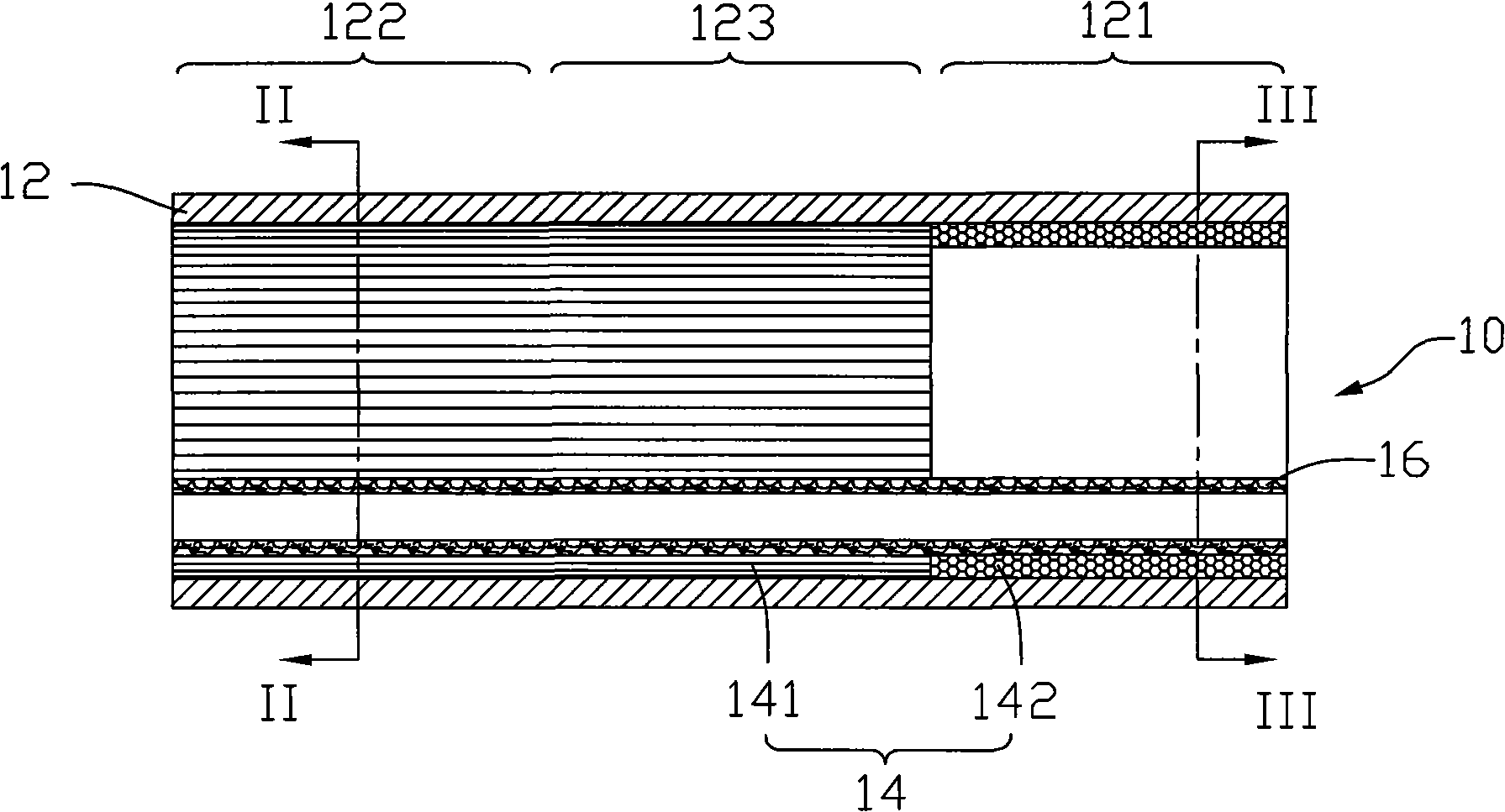
[0016] see figure 1 , the heat pipe 10 includes a tube body 12 , a capillary structure and a working fluid (not shown) filled in the tube body 12 .

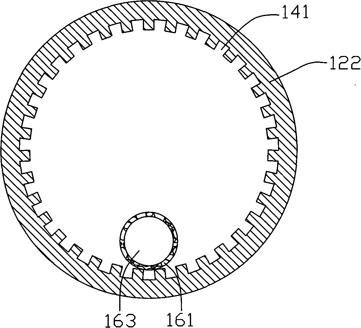
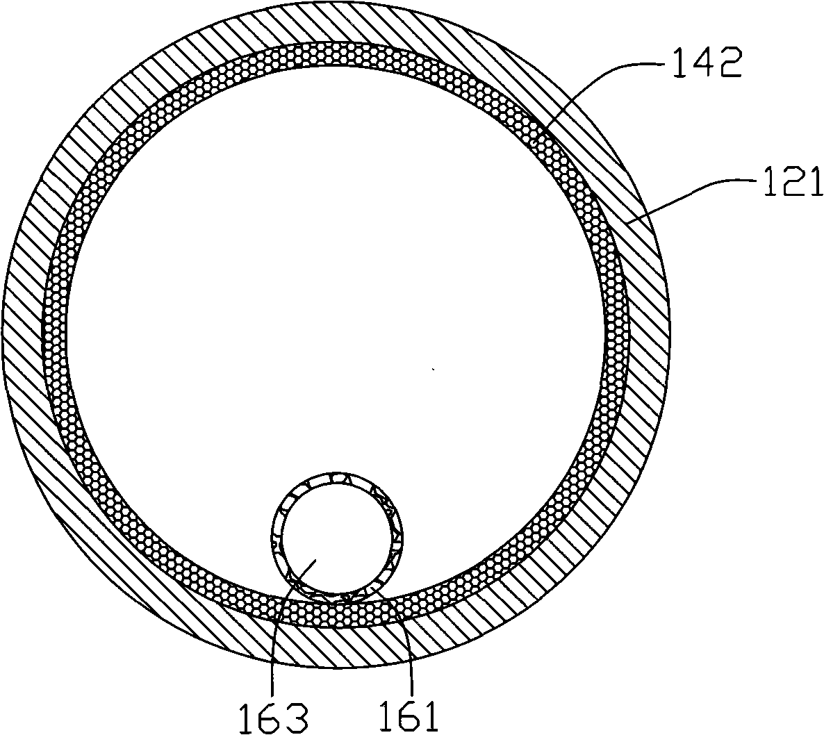
[0017] The pipe body 12 is made of copper and other materials with good thermal conductivity, which can transfer the heat generated by a heating element to the inside of the pipe body 12, which includes an evaporation section 121, a condensation section 122 and a connecting The evaporating section 121 and the adiabatic section 123 of the condensing section 122 .

[0018] The working fluid is filled in the tube body 12 and is a substance with a relatively low boiling point such as water, paraffin, alcohol, and methanol. The working fluid absorbs heat and evaporates from the evaporating section 121 of the pipe body 12, moves to the condensing section 122 with heat, condenses into a liquid after releasing heat in the condensing section 122, releases the heat, and flows back to the evaporating section 121 for the next step. A heat ...


PUM


Abstract

A heat pipe comprises a pipe body, a capillary structure in the pipe body and working fluid which is filled in the pipe body, wherein the heat pipe comprises an evaporating section and a condensing section along the pipe body direction, the capillary structure comprises a main capillary structure and an auxiliary capillary structure, wherein the main capillary structure is attached on the inner walls of the pipe body, the main capillary structure of the evaporating section has stronger capillary force than the main capillary structure of the condensing section, the auxiliary capillary structure comprises at least a haemal tube in hollow tube structure, wherein the haemal tube is extended between the evaporating section and the condensing section, a plurality of tiny pores are formed on the walls of the haemal tube, and one side of the haemal tube is contacted with the main capillary structure, thereby facilitating the capillary structure of the heat pipe to provide stronger capillary acting force and to have small liquid reflux resistance, and increasing the heat transfer property of the heat pipe.

Description

technical field [0001] The present invention relates to a heat pipe, in particular to a heat pipe for heat transfer. Background technique [0002] At present, heat pipes have been widely used in the heat dissipation of electronic components with large heat generation. When the heat pipe works, the low-boiling-point working fluid filled in the pipe body absorbs the heat generated by the heating electronic components in the evaporation section, evaporates and vaporizes, moves to the condensation section with heat, and liquefies and condenses in the condensation section to release the heat. The liquefied working fluid flows back to the evaporation section under the action of the capillary structure of the heat pipe wall, and the heat generated by the electronic components is dissipated through the circulating motion of the working fluid. [0003] During the working process of the heat pipe, when the capillary structure of the evaporating section of the heat pipe cannot provide...

Claims


Application Information

Patent Timeline
Patent Type & Authority Applications(China)
IPC IPC(8): F28D15/04
CPCF28D15/046
Inventor 张长生王肇浩刘睿凯白先声
Owner FU ZHUN PRECISION IND SHENZHEN
Why Eureka
Try Eureka