
Photoelectric coding counting device and photoelectric coding counter

The technology of a photoelectric coding and counting device is applied in the measurement and counting of household membrane gas meters, wireless automatic meter reading network, and measurement information transmission fields, which can solve the problems of gas meter measurement sensitivity, reduction in measurement accuracy, increase in transmission resistance of the character wheel, and inability to collect data. signal and other problems, to achieve the effect of improving reliability and anti-interference ability and saving costs

Inactive Publication Date: 2009-01-21
潘洪源
View PDF0 Cites 24 Cited by
  • Summary
  • Abstract
  • Description
  • Claims
  • Application Information

AI Technical Summary

Problems solved by technology

[0004] 1. Due to the magnetic attraction between the magnet and the metal sheet of the reed switch, the transmission resistance of the character wheel increases and shakes, resulting in a decrease in the measurement sensitivity and measurement accuracy of the gas meter;
[0005] 2. Reed switches and Hall elements rely on magnetic attraction and magnetic polarity changes to generate electrical signal pulses, and external magnetic interference cannot collect signals;

Method used


Image

  • Photoelectric coding counting device and photoelectric coding counter
  • Photoelectric coding counting device and photoelectric coding counter
  • Photoelectric coding counting device and photoelectric coding counter

Examples


Embodiment Construction

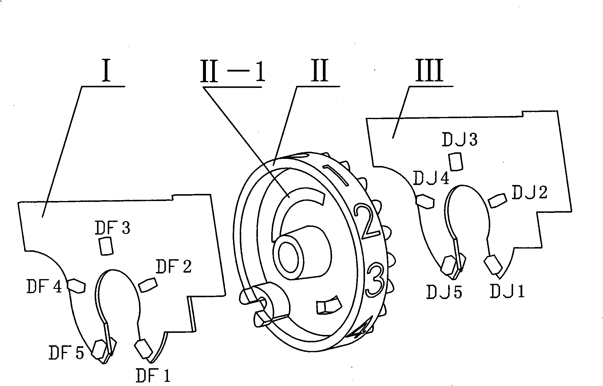
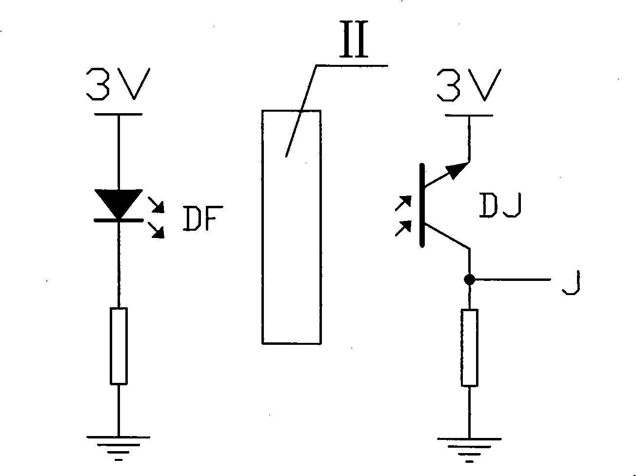
[0022] The photoelectric conversion principle of the present invention is as figure 1 As shown, when the 5 LED infrared emitting tubes (DF1~DF5) on the infrared emitting board I emit infrared light when powered on, the 5 infrared receiving tubes (DJ1~DJ5) on the infrared receiving board III receive the infrared light, and the infrared light or Pass through the coding hole II-1 of the counter character wheel II or be blocked by the counter character wheel II, and receive the infrared receiving tube (one of DJ1~DJ5) emitting infrared light from the infrared transmitting tube (one of DF1~DF5) The photoelectric conversion unit where it is located will be turned on, such as figure 2 As shown, at this time figure 2 The voltage at middle sampling point J is 0V, indicating a low level, represented by 0; when the infrared light is blocked by the counter character wheel II, that is, the corresponding infrared receiving tube does not receive the infrared light, at this time figure 2...


PUM


Abstract

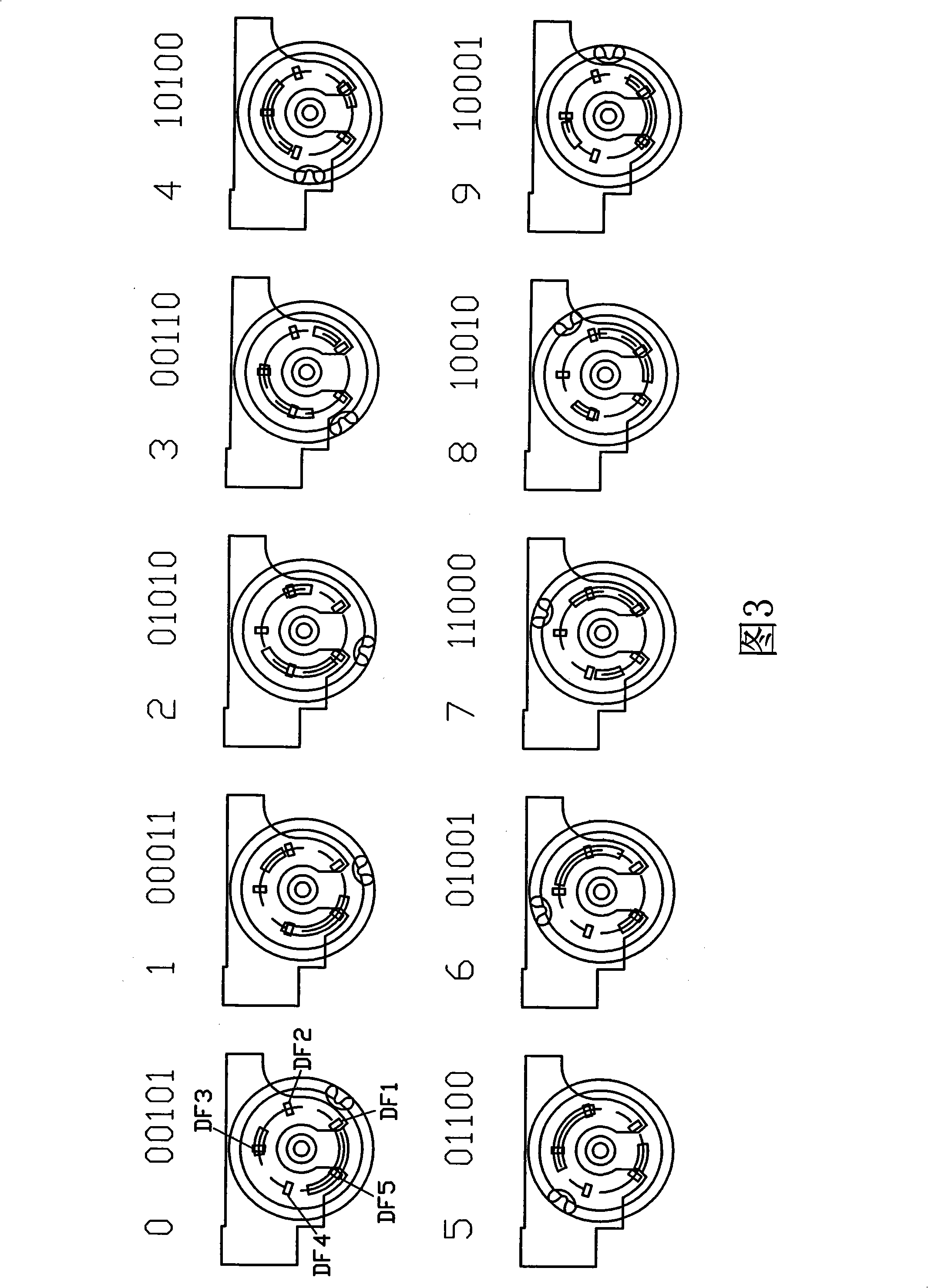
The invention discloses a photoelectric coding counting device and a photoelectric coding counter thereof, wherein the photoelectric coding counting device is provided with an infrared transmitting plate, a counter print wheel and an infrared receiver plate, and coding holes are arranged on the counter print wheel, and an infrared receiver tube can transform photoelectric signals into a group of binary codes according to whether infrared lights sent by an infrared transmitting tube pass through the coding holes and are received by the infrared receiver tube. The photoelectric coding counter comprises a counter bracket, a circuit board and five groups of photoelectric coding counting devices, wherein the circuit board is provided with a microprocessor, a photoelectric sampling circuit and a wireless transceiving circuit, wherein infrared receiver tubes in each group of photoelectric coding counting devices can transform the photoelectric signals of the infrared transmitting tubes in relative group into a group binary codes, each group of binary codes are transformed into some decimal digit value of the photoelectric coding counter after being decoded by the microprocessor, each decimal value can combine into an integral actual value, and the actual value is transmitted to a counter system through controlling the wireless transceiving circuit by the microprocessor. The device has simple structure design and accurate and reliable data collection, and can conveniently realize the wireless automatic meter reading and real-timely monitor the operation condition of a fuel gas meter.

Description

Technical field: [0001] The invention relates to a photoelectric coding and counting device based on a wireless sensor network and a photoelectric coding counter thereof, which are mainly used in metering and counting and metering information transmission of household membrane gas meters, and can conveniently form a wireless automatic meter reading network. Background technique: [0002] With the advancement of urbanization, the popularization and application of piped natural gas, and the increasing consumption of household membrane gas meters, the problems of production management, safety management, and meter reading management of gas operating enterprises have also become prominent. In order to adapt to the modern management of gas operating enterprises, there is an increasing demand for smart metering gas meters such as prepaid gas meters and remote automatic meter reading. At present, most of the counting sensor devices of smart gas meters are equipped with a reed switc...

Claims


Application Information

Patent Timeline
IPC IPC(8): G01D5/34G01F15/06G01F15/07G08C17/02
Inventor 潘洪源
Owner 潘洪源
Learn More