End cap board and motor rotor containing the same

A technology of motor rotor and end cover plate, applied in the direction of magnetic circuit rotating parts, magnetic circuit shape/style/structure, etc., can solve the problems of easy magnetic permeability of screws, increase in manufacturing cost and time, influence magnetic field, etc., and achieve stable embedding The effect of grouping magnetic bodies, reducing assembly costs and prolonging service life

Inactive Publication Date: 2009-01-21
SYST GEN
View PDF0 Cites 8 Cited by
  • Summary
  • Abstract
  • Description
  • Claims
  • Application Information

AI Technical Summary

Problems solved by technology

[0014] However, this patented technology is fixed by screws, which are easy to conduct magnetism and affect the magnetic field
At the same time, not only tools are needed to lock the screws, but also the number of components is time-consuming and labor-intensive, causing inconvenience in assembly
Furthermore, 8 screws must be used in this patented technology. In order to keep the center of gravity stable, screws with the same weight and corresponding nuts must be used; in this way, the selection of materials must be careful, because even the same batch of materials will be different weight, and special technology and procedures must be used for material selection, thus greatly increasing manufacturing cost and time
Moreover, since the motor rotor must maintain a rotating motion during use, this type of motion plus vibration can easily loosen the screws, causing the permanent magnet to shift, affecting the service life of the motor and the motor rotor

Method used


Image

  • End cap board and motor rotor containing the same
  • End cap board and motor rotor containing the same
  • End cap board and motor rotor containing the same

Examples


Embodiment Construction

[0062] Embodiments of the present invention are described below through specific examples, and those skilled in the art can easily understand other advantages and effects of the present invention from the content disclosed in this specification.

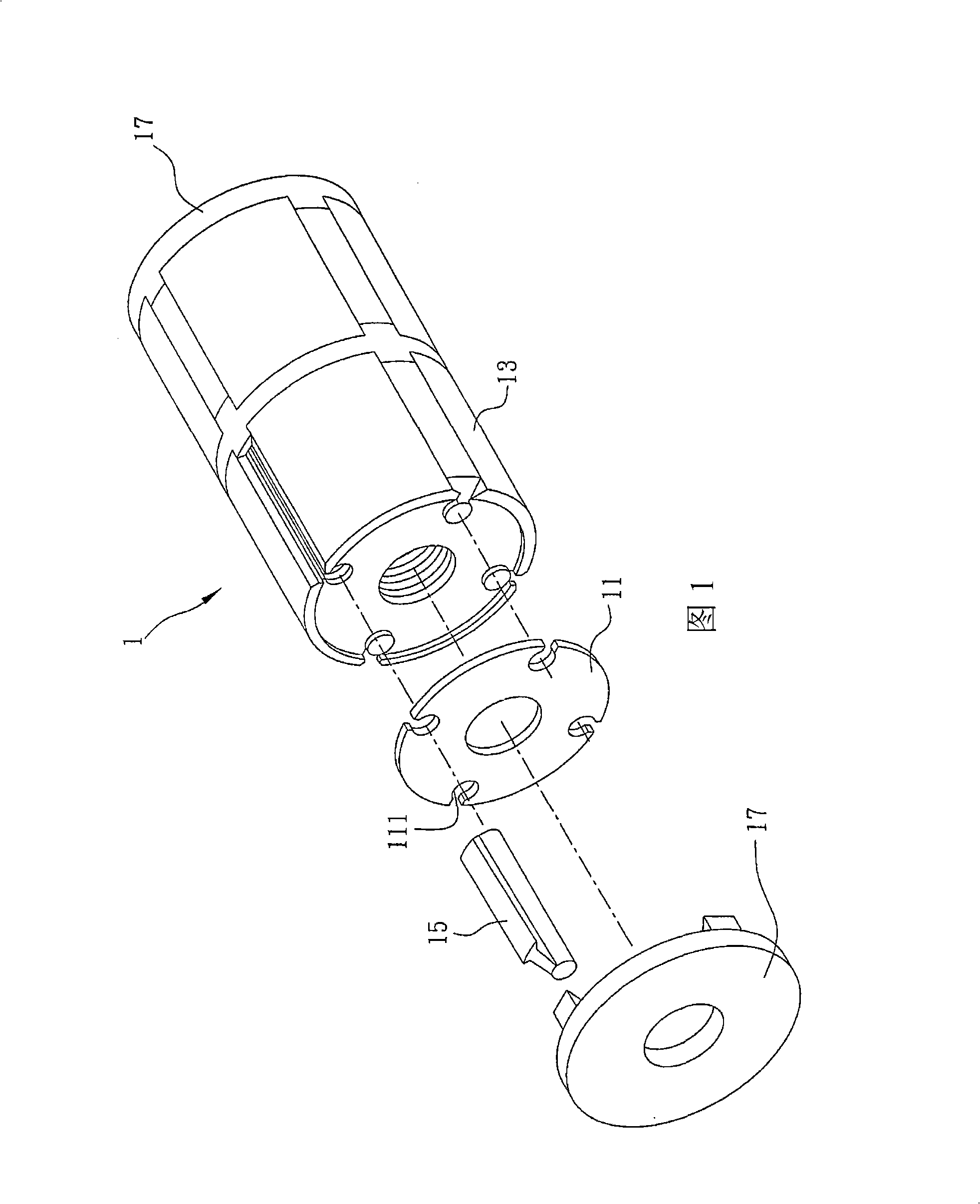
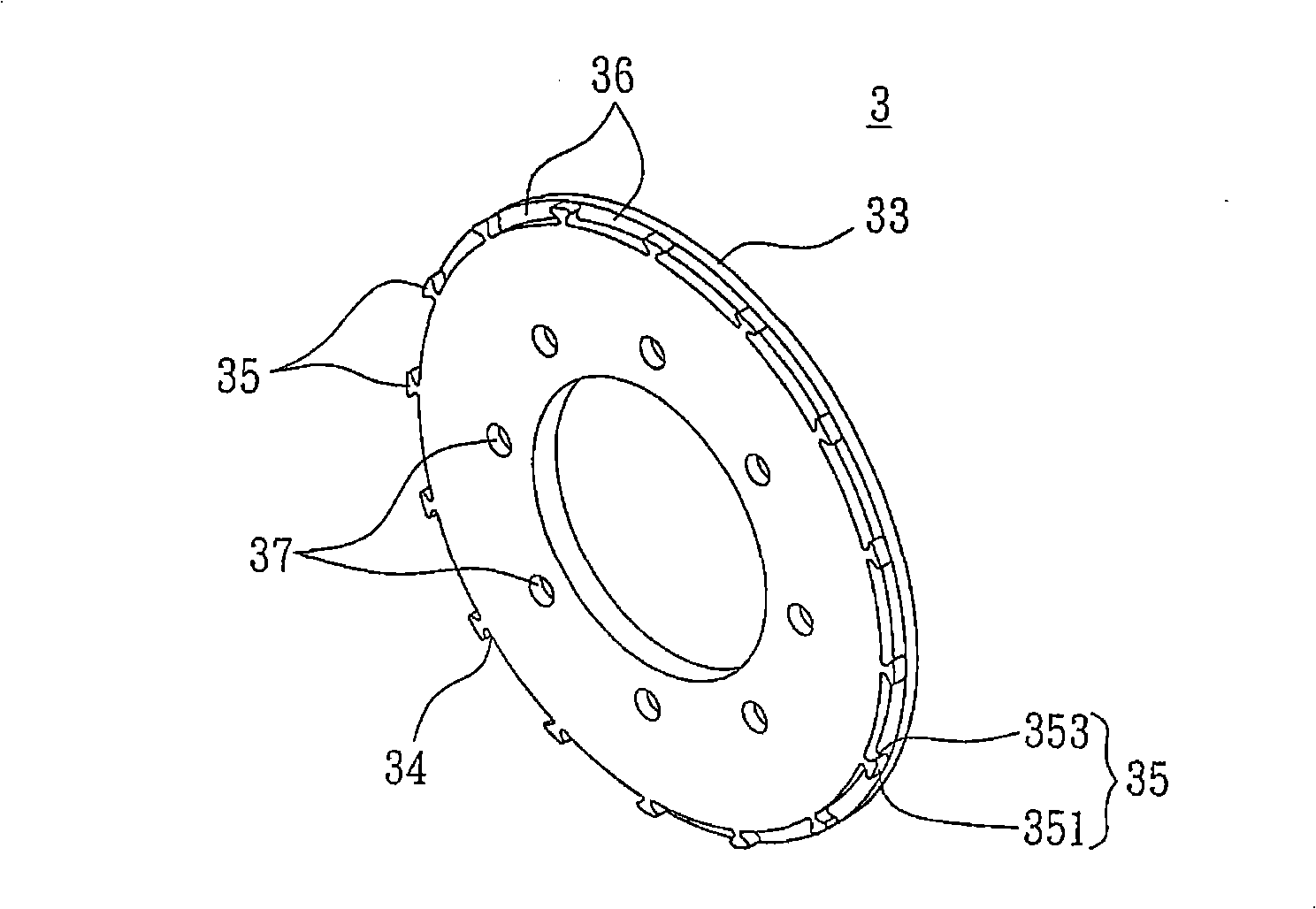
[0063] Figure 3A and Figure 3B It is a structural schematic diagram and a partial cross-sectional view respectively showing an embodiment of the end cover plate 3 of the present invention. The end cover plate 3 is supplied for being combined with the end surface of the rotating shaft of the motor rotor, and is used for fixing and surrounding the multiple walls arranged around the rotating shaft. A magnetic body (to be stated later), such as Figure 3A and Figure 3B As shown, the end cover plate 3 has a first surface 31 facing the end surface of the rotating shaft and an opposite second surface 32. The first surface 31 has a plurality of radially inward recesses from the edge and corresponding to each of the magnetic bodies. The...


PUM


Abstract

The present invention relates to an end cover plate which is used in a plurality of magnetic bodies which are fixedly arranged around the peripheral wall of a rotating shaft. The surface of the end cover plate is provided with a plurality of slots, which are concave from the edge in the radial direction and correspond to the magnetic bodies. And the end cover plate is used for correspondingly fixing the ends of the magnetic bodies, so as to fix the magnetic bodies on the rotating shaft. In addition, the present invention also provides a motor rotor with the end cover plate.

Description

technical field [0001] The invention relates to a motor rotor, in particular to a magnetically driven motor rotor and an end cover plate thereof. Background technique [0002] Motors (electric motors) are used to convert electrical energy into mechanical energy to provide output rotational motion. Of course, in addition to directly providing rotational motion, the output rotational mechanical energy can be converted into linear motion or vibration motion with different mechanisms. [0003] A motor for providing rotational motion is composed of a rotor and a stator, wherein the stator is a fixed part for providing a surrounding magnetic field, and the rotor is a rotatable part according to the magnetic field. A common rotor is composed of a rotating shaft and a plurality of permanent magnets. The rotating shaft is usually formed by stacking a plurality of silicon steel sheets, and the plurality of permanent magnets are adhered to the surrounding wall of the rotating shaft at ...

Claims


Application Information

Patent Timeline
Patent Type & Authority Applications(China)
IPC IPC(8): H02K1/27H02K1/28
Inventor 杨世仁涂弘森陈益兴杨镇嘉陈仲恩
Owner SYST GEN
Why Eureka
Try Eureka