Solid heat carrier rapid pyrolysis method and apparatus

A solid heat carrier, pyrolysis technology, applied in the direction of direct heating dry distillation, petroleum industry, coke oven, etc., can solve the problems of lack of adjustment means, large pressure difference, influence of hot ash distribution valve operation, etc., to achieve good fuel adaptability , temperature controllable, enhance the effect of balance ability

Active Publication Date: 2009-01-28
INST OF ENGINEERING THERMOPHYSICS - CHINESE ACAD OF SCI
View PDF1 Cites 52 Cited by
  • Summary
  • Abstract
  • Description
  • Claims
  • Application Information

AI Technical Summary

Problems solved by technology

However, due to the large pressure difference between the two passages where the circulating ash returns to the furnace, this will have a certain impact on the operation of the hot ash distribution valve
In addition, when the actual coal used is quite different from the designed coal, it may be difficult to match the heat released by combustion with the heat required for pyrolysis, and the existing methods lack adjustment means

Method used


Image

  • Solid heat carrier rapid pyrolysis method and apparatus
  • Solid heat carrier rapid pyrolysis method and apparatus
  • Solid heat carrier rapid pyrolysis method and apparatus

Examples


Embodiment 1

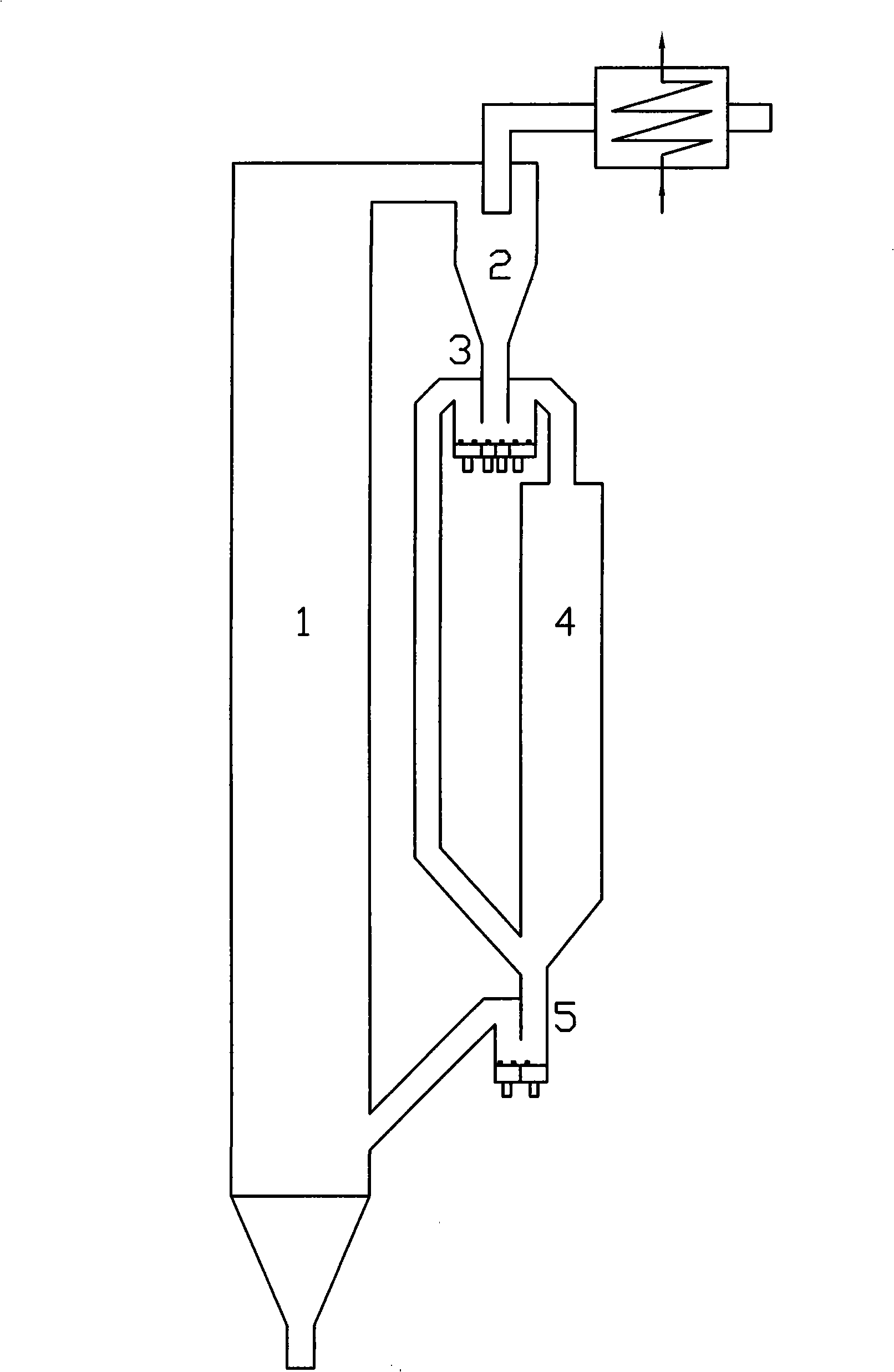
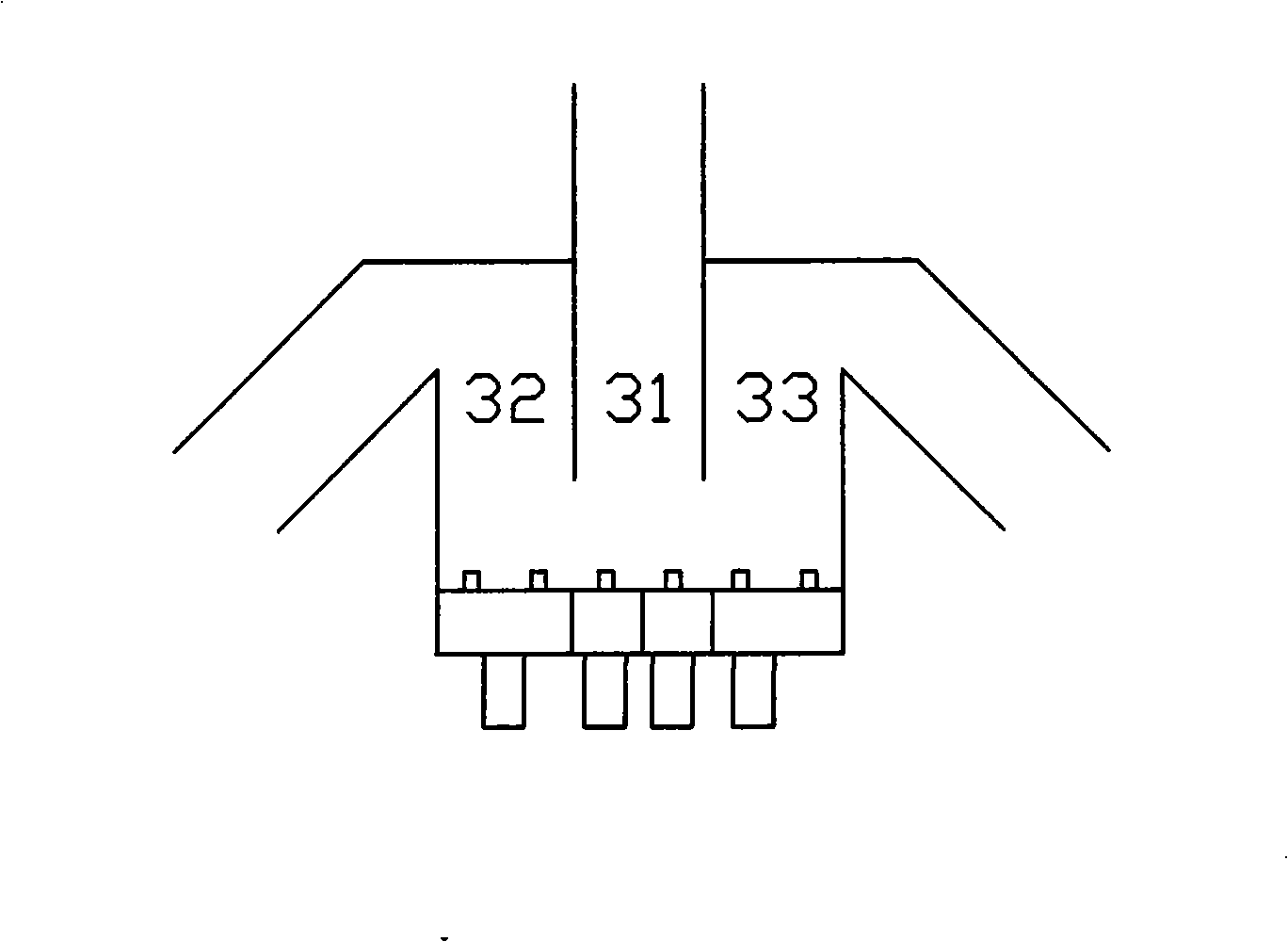
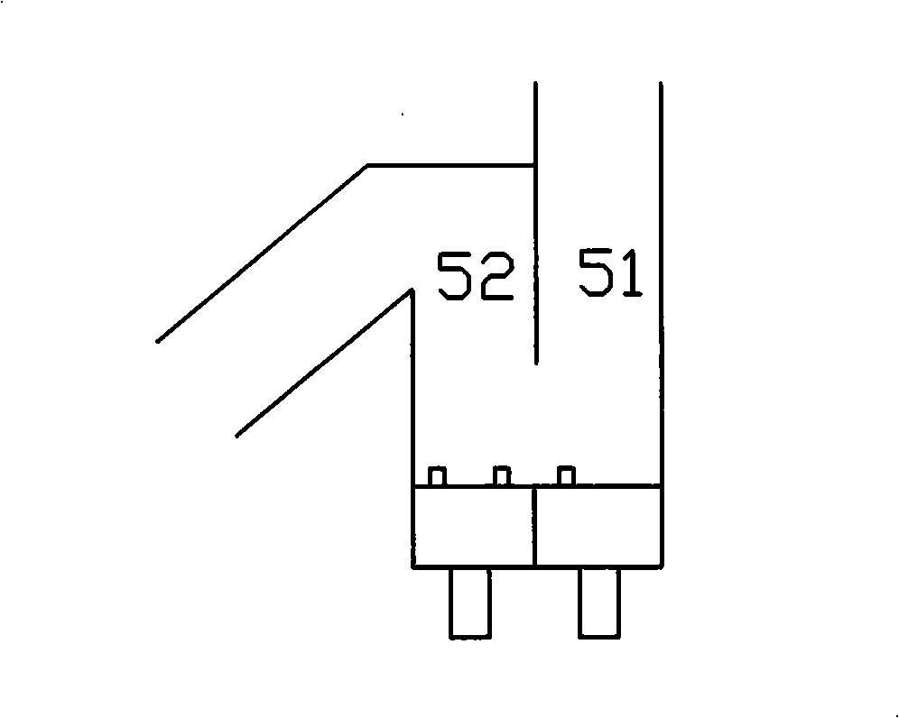
[0034] like figure 1 As shown, the fuel is burned in the circulating fluidized bed combustion chamber 1, and the high-temperature circulating ash in the flue gas captured by the cyclone separator 2 is divided into two parts by the pneumatically controlled hot ash distributor 3, and one part enters the moving bed as a solid heat carrier The pyrolysis chamber 4 provides heat for the pyrolysis of the fuel in the pyrolysis chamber 4, and the pyrolysis gas is drawn from the pyrolysis chamber 4; the other part of the circulating ash does not enter the pyrolysis chamber 4, and is discharged from the bottom of the pyrolysis chamber 4 with the semi-coke and The circulating ash returns to the combustion chamber 1 through the differential bed return device 5 together.

[0035] The solid heat carrier rapid pyrolysis device of the present invention includes: a circulating fluidized bed combustion chamber 1 connected in sequence, a cyclone separator 2, a pneumatically controlled hot ash dis...

Embodiment 2

[0037] like Figure 4 As shown, the difference between Embodiment 2 and Embodiment 1 is that a hot ash cooler 6 is added.

[0038] The fuel is burned in the circulating fluidized bed combustion chamber 1, and the high-temperature circulating ash in the flue gas captured by the cyclone separator 2 is divided into two parts by the pneumatically controlled hot ash distributor 3, and one part enters the moving bed pyrolysis chamber as a solid heat carrier 4. Provide heat for fuel pyrolysis, and the other part of the circulating ash does not enter the pyrolysis chamber 4. After the heat is released by the hot ash cooler 6, it is fed back through the differential bed together with the semi-coke and circulating ash discharged from the bottom of the pyrolysis chamber 4. The device 5 returns to the combustion chamber 1 .

[0039]The solid heat carrier rapid pyrolysis device provided by the present invention includes: a circulating fluidized bed combustion chamber 1 connected in sequen...


PUM


Abstract

The invention relates to a method and a device for the quick pyrolysis of solid heat carriers; the device comprises a circulating fluidized bed combustor, a cyclone separator, an aerodynamic hot ash distributor, a pyrolysis chamber and a differential bed material return device; fuel is burnt in the circulating fluidized bed combustor, the high-temperature circulation ash of flue gas collected by the cyclone separator is divided into two parts by the hot ash distributor aerodynamically controlled, one part enters the pyrolysis chamber of a moving bed as the solid heat carrier to supply heat for flue pyrolysis, the other part does not enter the pyrolysis chamber but returns to the combustor, together with the semicoke and circulation ash discharged from the bottom of the pyrolysis chamber through the differential bed material return device. The method and the device for the quick pyrolysis of solid heat carrier provided by the invention can distribute the high-temperature circulation ash between combustion and pyrolysis loops stably and reliably, with controllable temperature of the pyrolysis chamber, strengthen the balance capacity between combustion and pyrolysis by virtue of a hot ash cooler, have good adaptability of the flue, and can be used for the pyrolysis of coal, biomass and other carbonaceous refuses.

Description

technical field [0001] The invention relates to a coal pyrolysis method and a coal pyrolysis device. technical background [0002] There are two types of coal pyrolysis chambers commonly used at present, namely moving bed gasification chamber and bubbling bed gasification chamber. In the moving bed gasification chamber, semi-coke is often returned to the combustion chamber in a self-flowing manner, which cannot control the residence time of the material in the gasification chamber and affects the conversion rate of carbon; while the returning material on a conventional circulating fluidized bed boiler The device is also not suitable here, because the particle size of the semi-coke is much larger than that of the boiler circulating ash, and the fluidity is also very different. The bubbling bed gasification chamber can conveniently control the return of materials, but because the fluidization gas velocity is higher than that of the moving bed, the particles entrained by elutr...

Claims


Application Information

Patent Timeline
Patent Type & Authority Applications(China)
IPC IPC(8): C10B49/10
Inventor 吕清刚那永洁高鸣刘琦王东宇包绍麟孙运凯贺军
Owner INST OF ENGINEERING THERMOPHYSICS - CHINESE ACAD OF SCI
Why Eureka
Try Eureka