Flywheel gluing system and motor rotor production device

A flywheel and gluing technology, which is applied in the manufacture of motor generators, stator/rotor bodies, coatings, etc., can solve problems such as uneven gluing, thin outer walls of flywheels that are difficult to clamp, and dripping into the work area.

Inactive Publication Date: 2019-02-15
陈荣乾
View PDF0 Cites 10 Cited by
  • Summary
  • Abstract
  • Description
  • Claims
  • Application Information

AI Technical Summary

Problems solved by technology

The deficiencies of the existing assembly equipment are: 1. The steel flywheel is heavy, and the existing flywheel feeding device needs to use power input, which not only has high cost but also has low feeding stability and accuracy; 2. The outer wall of the flywheel is thin and difficult to clamp, The flywheel and the pole cover need to be glued. The existing glue coating equipment uses the glue head to move the workpiece to be stationary. Not only is the glue applied unevenly, but the glue is easy to mess up on other parts, and there will be dust on the surface of the workpiece before glue coating. , di

Method used


Image

  • Flywheel gluing system and motor rotor production device
  • Flywheel gluing system and motor rotor production device
  • Flywheel gluing system and motor rotor production device

Examples


Embodiment Construction

[0031] The present invention will be further described below in conjunction with the accompanying drawings and embodiments.

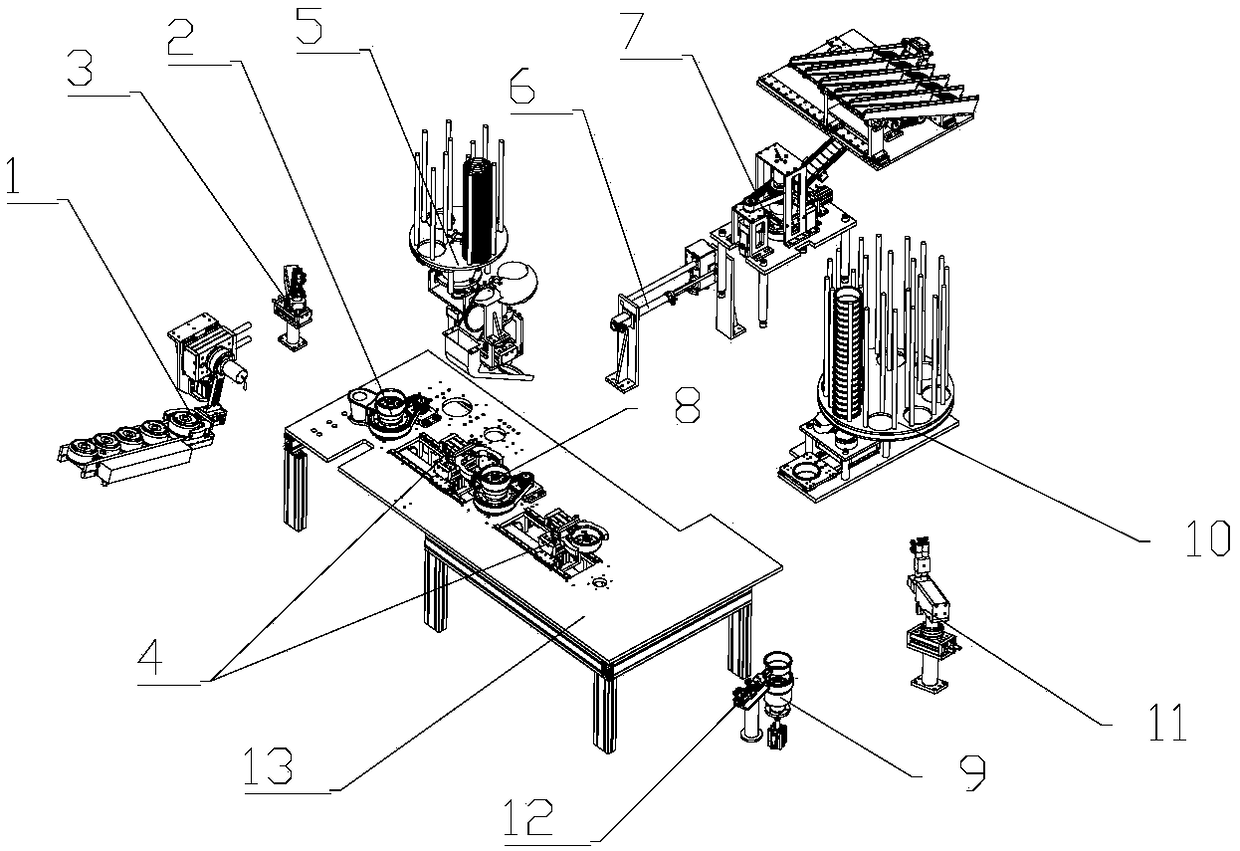
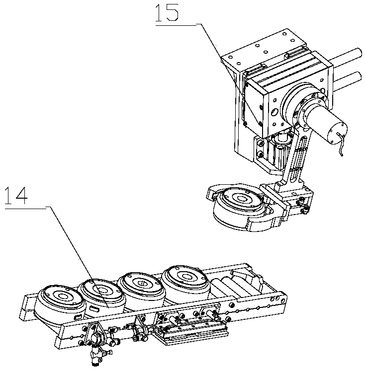
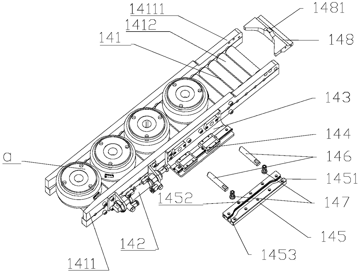
[0032] Such as Figure 1-Figure 19 As shown, the motor rotor production equipment includes a frame 13 and a flywheel feeding device 1 on it, a flywheel gluing system, a handling manipulator device 4, a guard ring sorting system, a magnetic tile assembly system and a pole cover assembly system.

[0033] The flywheel gluing system includes the first positioning workbench 2 and the flywheel gluing device 3, the positions of the flywheel feeding device 1 and the flywheel gluing device 3 correspond to the first positioning workbench 2; the grommet sorting system includes the grommet sorting device 5 and the retaining ring handling device 6; the magnetic tile assembly system includes a magnetic tile feeding assembly device 7 and a second positioning workbench 8; the pole cover assembly system includes a third positioning workbench 9, a pole cover sorting and ...


PUM


Abstract

The invention relates to the technical field of motor rotor production. The flywheel gluing system comprises a first positioning working table and a flywheel gluing device; the first positioning working table includes a fixing frame, a second air cylinder, a spline shaft, a jacking cone disk, a first belt transmission assembly, a positioning base, a positioning pinch plate, a glue collecting bucket collecting assembly, a rotating connecting sleeve and a first motor; and the flywheel gluing device comprises a second rotating air cylinder installation frame, a second rotating air cylinder, a rotating arm, a third linear rail shifting assembly, a second air cylinder and a first glue scraping machine. The flywheel gluing system has the advantages that flywheel gluing is uniform, glue cannot drip into a working area, and the glue bonding effect is better.

Description

technical field [0001] The invention relates to the technical field of motor rotor production, in particular to the field of magneto rotor assembly. Background technique [0002] The magneto rotor uses the electric motor to drive the flywheel to rotate at high speed, and when needed, the flywheel drives the generator to generate electricity, so that energy is used efficiently. The rotor of the magneto mainly includes a flywheel, a guard ring, a magnetic tile and a pole cover, and some processes in this process also involve a glue coating process. The assembly process is to apply glue to the inner wall of the flywheel after feeding the flywheel, then install the retaining ring and magnetic tiles, and install the outer wall of the pole cover in the flywheel after applying glue. The deficiencies of the existing assembly equipment are: 1. The steel flywheel is heavy, and the existing flywheel feeding device needs to use power input, which not only has high cost but also has low...

Claims


Application Information

Patent Timeline
IPC IPC(8): B05C13/02B05C11/10B05C9/02H02K15/02H02K15/12B08B1/00B08B1/02
CPCB05C9/02B05C11/1039B05C13/02B08B1/001B08B1/02H02K15/02H02K15/12
Inventor 陈荣乾
Owner 陈荣乾
Why Eureka
Try Eureka