
Electronic device with function of controlling fan rotating speed and control method thereof

An electronic device and fan speed technology, applied in the direction of speed/acceleration control, control/regulation system, non-electric variable control, etc., can solve the problems of the cooling system's cooling capacity decline, stuffing into the air outlet, speed reduction, etc., to improve the heat dissipation effect Effect

Inactive Publication Date: 2009-01-28
MITAC COMP (SHUN DE) LTD +1
View PDF0 Cites 21 Cited by
  • Summary
  • Abstract
  • Description
  • Claims
  • Application Information

AI Technical Summary

Problems solved by technology

[0006] Although this fan speed control system solves the problem of increasing the temperature of the heat-generating component when the electronic device executes the program, the fan needs to be installed on the heat-generating component that is most likely to increase in temperature, and a reference fan speed is set. In order to achieve the best heat dissipation effect, that is to say, the speed of the reference fan will be set higher than the speed of the general fan, which will increase the noise
[0007] Moreover, the control method of the above-mentioned fan speed control system will also cause the heat dissipation capacity of the heat dissipation system to decline due to other problems, such as the electronic device is placed in the sky, the speed of the fan decreases with time, and obstacles are inserted into the air outlet.

Method used


Image

  • Electronic device with function of controlling fan rotating speed and control method thereof
  • Electronic device with function of controlling fan rotating speed and control method thereof
  • Electronic device with function of controlling fan rotating speed and control method thereof

Examples


Embodiment Construction

[0027] The electronic device with fan speed control function according to the preferred embodiment of the present invention will be described below with reference to related drawings, wherein the same components will be described with the same reference symbols.

[0028] In the following preferred embodiments of the electronic device with fan speed control function of the present invention, in order to facilitate understanding, the symbols of the components in the following embodiments follow the symbols of the same components as in the previous embodiment.

[0029] Please also refer to Figure 4 and Figure 5, Figure 4 It is an electronic device with fan speed control function of the present invention, and Fig. 5 is a schematic diagram of the fan speed control equation curve of the present invention, in Figure 4 Among them, the electronic device 41 with fan speed control function at least includes an air inlet 411, an air outlet 412, a heating element 413, a fan 414, a sens...


PUM


Abstract

The present invention discloses an electronic device with a fan speed control function and a control method thereof. The electronic device with the fan speed control function at least comprises an air inlet, an air outlet, a heating assembly, a fan, a sensing module and a control module, wherein the sensing module is also provided with a first sensing assembly which is arranged at the air inlet so as to detect a first temperature at the air inlet, and a second sensing assembly which is arranged at the air outlet so as to detect a second temperature at the air outlet. The difference between the first temperature and the second temperature is determined according to an equation of the control module so as to adjust the rotation rate of the fan. The device utilizes the sensing assemblies, which are respectively arranged at the air inlet and the air outlet, to achieve the compensation of the fan speed, improve the heat elimination effect, and reduce the noise during using.

Description

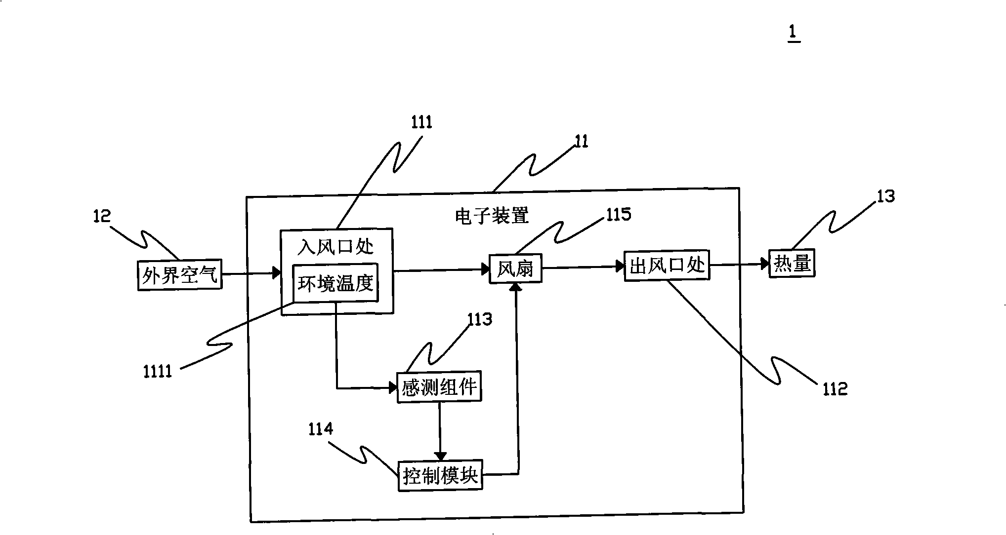
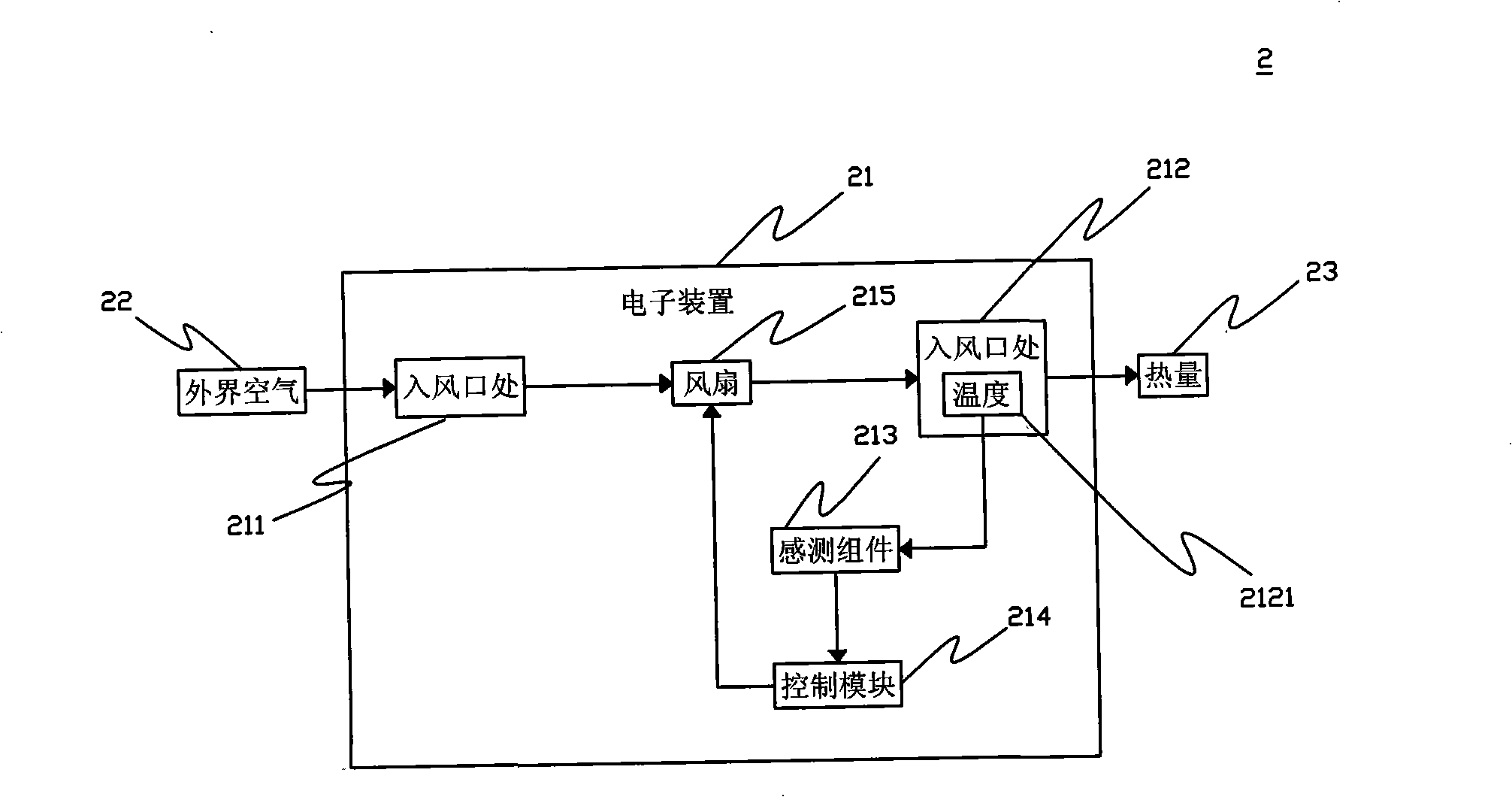
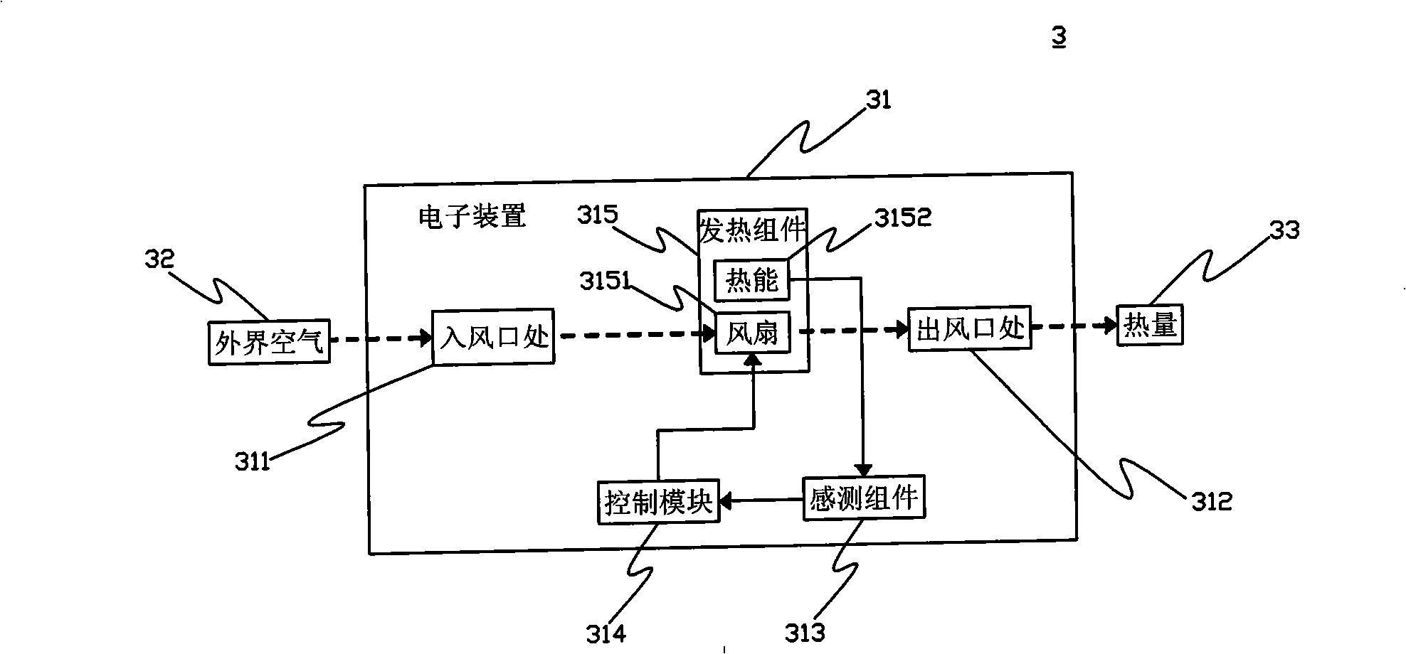
technical field [0001] The invention relates to an electronic device and a control method thereof, in particular to an electronic device with a fan speed control function and a fan speed control method. Background technique [0002] see figure 1 , is a schematic diagram of a conventional fan speed control system. The fan speed control system 1 includes an electronic device 11 , which further includes an air inlet 111 , an air outlet 112 , a sensing component 113 , a control module 114 and a fan 115 . In this figure, when the outside air 12 enters from the air inlet 111 of the electronic device 11, an ambient temperature 1111 will be generated, and the sensing component 113 will sense the ambient temperature 1111 and send a signal to the control module 114 , when the ambient temperature 1111 rises, the control module 114 controls the rotation speed of the fan 115 to increase, so that the air outlet 112 can dissipate more heat 13 . [0003] see next figure 2 , is a schema...

Claims


Application Information

Patent Timeline
IPC IPC(8): H05K7/20G05D13/66
Inventor 邱一平
Owner MITAC COMP (SHUN DE) LTD
Learn More