
Side stand switch

A technology on the side of switches and vehicles, which is applied in the direction of electric switches, bicycle brackets, bicycle accessories, etc., which can solve the problems of increased number of parts in the working process, easy increase in weight, difficult switching angle, etc., to achieve easy production process and improved installability , The effect of reducing the number of parts

Active Publication Date: 2009-01-28
HONDA MOTOR CO LTD
View PDF1 Cites 10 Cited by
  • Summary
  • Abstract
  • Description
  • Claims
  • Application Information

AI Technical Summary

Problems solved by technology

[0005] However, the technique of Patent Document 1 is a structure in which the side stay shaft is rotatably supported on the vehicle frame by a bolt member, and in addition, the rotary switch is mounted on the frame provided by a mounting screw. Due to the structure of the threaded hole on the head of the bolt member, there are problems in the work process during installation and the number of parts increases
In addition, in this structure, in order to fasten with the above-mentioned mounting screws without deformation, etc., it is necessary to form the structural parts of the rotary switch with metal, etc., and there is also a problem that the weight etc. tend to increase.
[0006] In addition, in the technique of Patent Document 1, a substantially semicircular plate whose center point is the same as the rotation axis of the side stay is applied to the contact point on the movable side of the rotary switch, so it is difficult to increase the energization angle of the switch.
There is still room for further improvement in the structure of further increasing the energization angle of the rotary switch and uniforming the contact pressure between the movable contact and the fixed contact.

Method used


Image

  • Side stand switch
  • Side stand switch
  • Side stand switch

Examples


Embodiment Construction

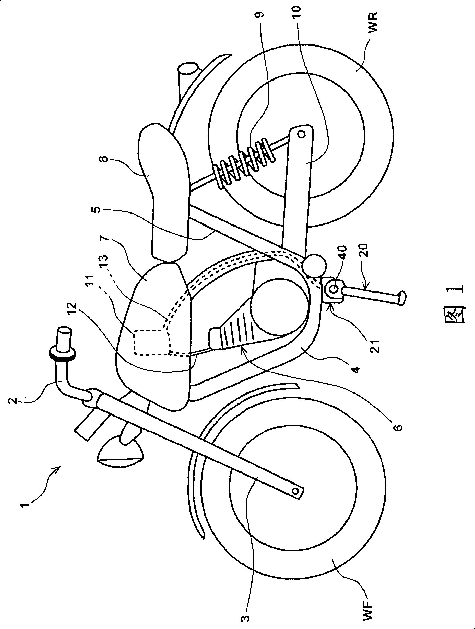
[0078] Hereinafter, preferred embodiments of the present invention will be described in detail with reference to the drawings. FIG. 1 is a side view of a motorcycle to which a side stand switch according to an embodiment of the present invention is applied. A front fork 3 steerable by a handle 2 is attached to the vehicle body front side of a main frame 4 of the motorcycle 1 , and a front wheel WF is rotatably pivotally supported on a lower end portion of the front fork 3 . The main frame 4 is connected to a rear frame 5 that supports a seat 8 on which a passenger sits on the rear side of the vehicle body. In addition, one end of the swing arm 10 is connected below the main frame 4, and the swing arm 10 is suspended by the rear shock absorber 9 mounted on the rear frame 5 so as to be swingable. On the other end of the swing arm 10, the shaft The rear wheel WR rotated by the driving force generated by the engine 6 is supported.

[0079] The bracket 21 is installed under the v...


PUM


Abstract

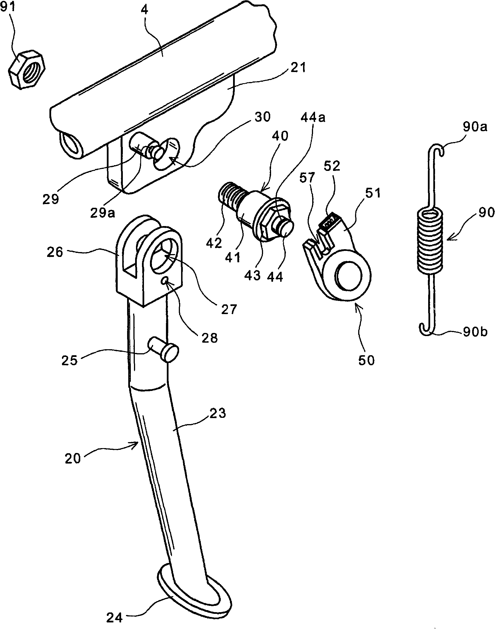
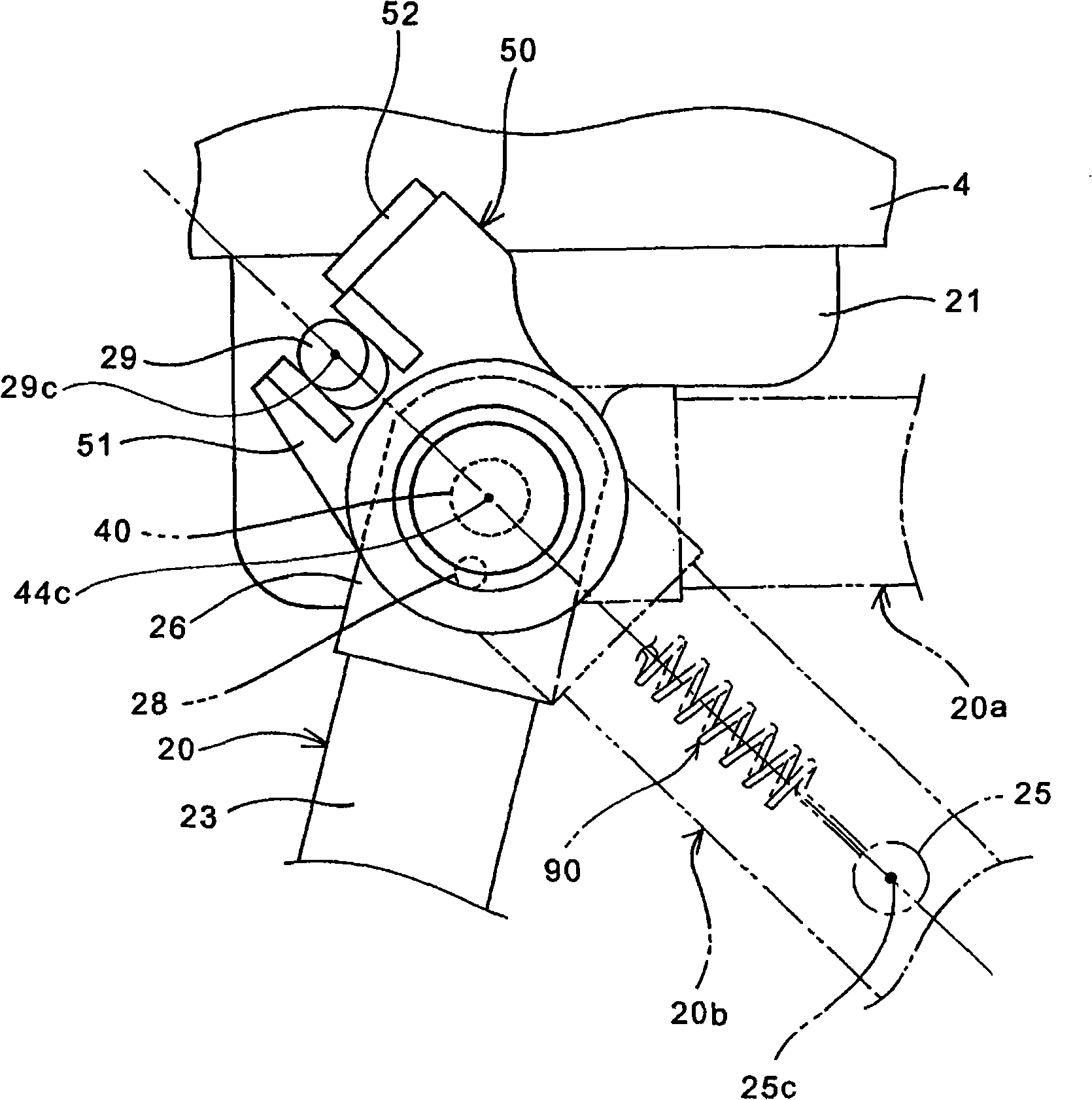
A side stand switch that has increased assembling easiness, that has reduced number of parts, and that is reduced in weight. A switch unit (50) is attached to a pivot bolt (40) for rotatably supporting a side stand bar (20) at a bracket (21) on the vehicle body side. The switch unit (50) is constructed from a resin base (51) and a rotary (53) and detects the rotational position of the side stand bar (20). A first engagement mechanism (62) constructed from a groove and a ridgeis provided between a tubular section (54) formed at the rotary (53) and an engagement shaft (44), and a second engagement mechanism (63) constructed from a groove and a ridge is provided between the base (51) and the tubular section (54). When a positioning pin (55) formed at one end of the rotary (53) is engaged with a pin hole (28) of a pivot section (26), the rotary (53) to which a movable contact of a sheet spring is attached is rotated integrally with the side stand bar (20) to change a switch output from a connector (52).

Description

technical field [0001] The present invention relates to a side stand switch, and more particularly to a side stand switch capable of improving assemblability and achieving reduction in the number of parts and weight reduction. Background technique [0002] Conventionally, for a side stay of a motorcycle, a structure is known in which a switch for determining whether the side stay is in the storage position or the protruding position is mounted near the side stay. [0003] Patent Document 1 discloses a side stay of a motorcycle in which a rotary switch is attached to a rotation shaft of the side stay. [0004] Patent Document 1: Japanese Patent Publication No. 6-31038 [0005] However, the technique of Patent Document 1 is a structure in which the side stay shaft is rotatably supported on the vehicle frame by a bolt member, and in addition, the rotary switch is mounted on the frame provided by a mounting screw. Because of the structure of the threaded hole at the head of th...

Claims


Application Information

Patent Timeline
Patent Type & Authority Applications(China)
IPC IPC(8): B62H1/02H01H21/32
CPCH01H21/28H01H19/18B62H1/02H01H19/58H01H21/32
Inventor 中泽祥浩角田敬中岛广幸竹中正彦乾秀二郎
Owner HONDA MOTOR CO LTD
Learn More