Assembling structure of crankshaft and rotor

An assembly structure and crankshaft technology, applied in the field of compressors, can solve problems affecting motor performance, increasing equipment cost, structural changes, etc., to achieve the effects of saving assembly processes, improving fixing strength, and avoiding degaussing problems

Inactive Publication Date: 2009-02-04
LG ELECTRONICS (TIANJIN) APPLIANCES CO LTD
View PDF0 Cites 8 Cited by
  • Summary
  • Abstract
  • Description
  • Claims
  • Application Information

AI Technical Summary

Problems solved by technology

Although the thermal charging process can prevent the mutual rotation between the rotor and the crankshaft within a certain range, and fix the relative position of the crankshaft and the rotor, the process conditions of heating and thermal charging in this process are not easy to control, which is labor-intensive and time-consuming, and the scrap rate is high
(1) The hot loading process needs to be heated. Improper control of the heating temperature will cause changes in the material structure of the heated workpiece, reduce its service life, and cause hidden dangers; if the temperature is too low, the assembly of the workpiece cannot be completed
(2) The hot charging process conditions are not easy to control, resulting in a high scrap rate, causing waste and increasing costs
(3) Hot charging equipment needs to be configured, which increases equipment costs
(4) For permanent magnet motors, if the crankshaft and rotor are assembled by shrink-fitting process, it is easy to cause degaussing problems, which will affect the performance of the motor

Method used


Image

  • Assembling structure of crankshaft and rotor
  • Assembling structure of crankshaft and rotor
  • Assembling structure of crankshaft and rotor

Examples


Embodiment Construction

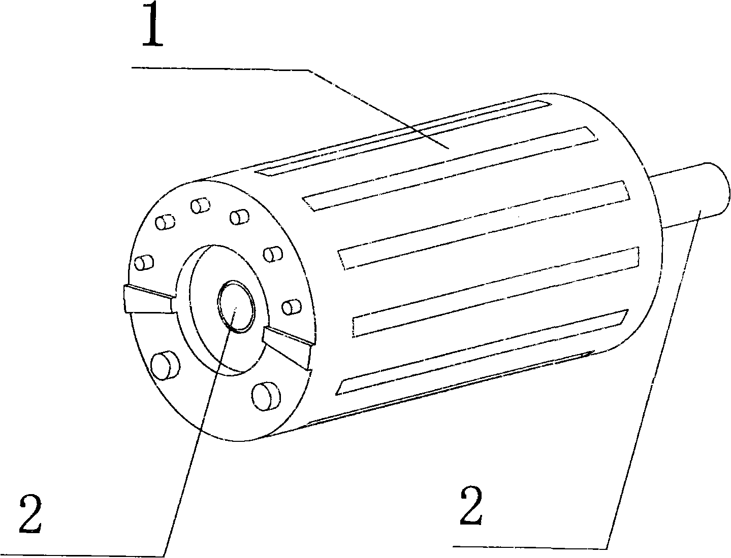
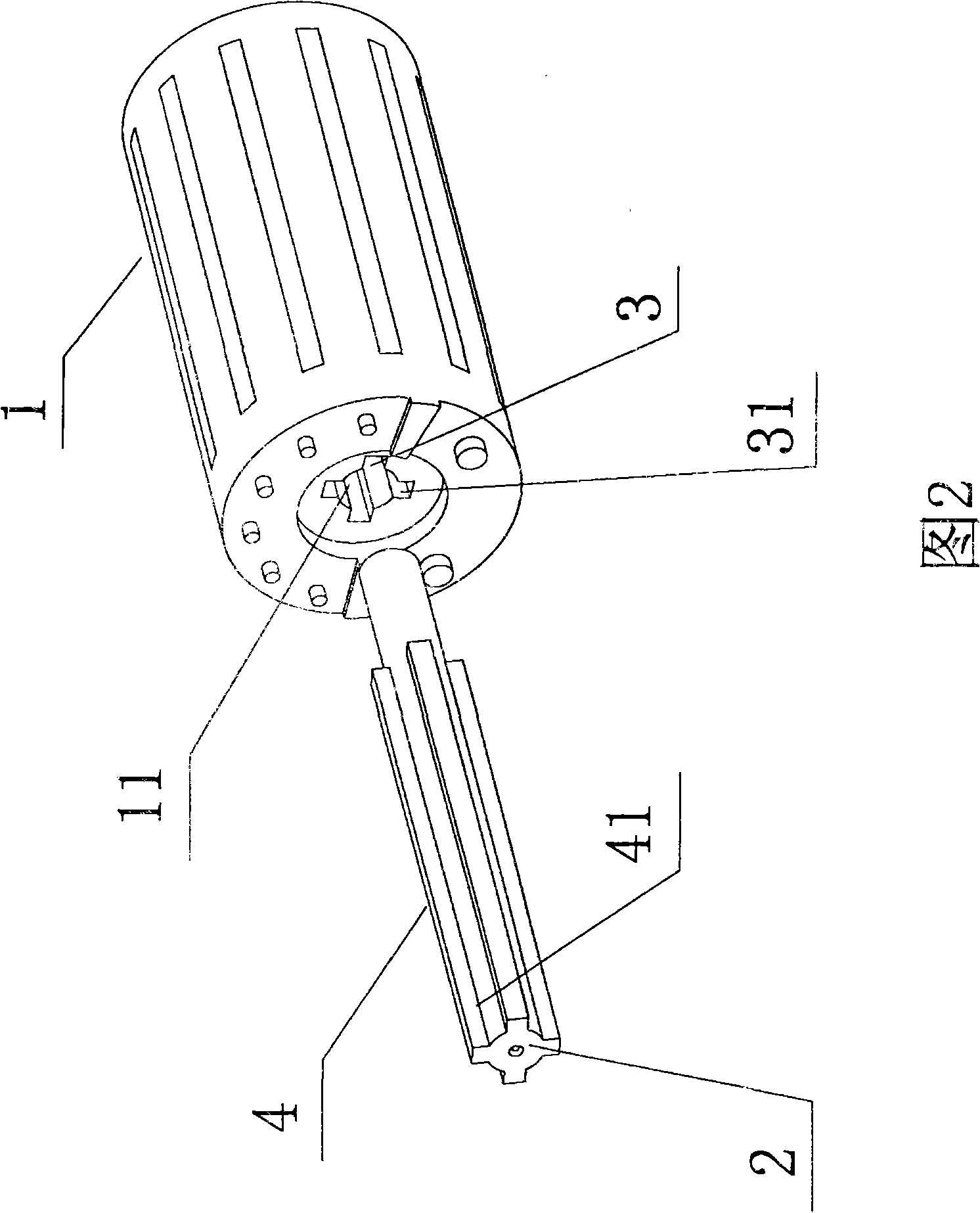
[0018] Referring to shown in Fig. 2, the assembly structure of crankshaft and rotor of the present invention, it comprises crankshaft, rotor, and the long axis portion of crankshaft is fixed in the shaft hole of rotor; There is more than one concave clamping position, and the outer surface of the long axis of the crankshaft 2 is provided with a corresponding convex structure corresponding to the clamping position, and the crankshaft and the rotor are assembled by means of the convex structure and the concave clamping position. One.

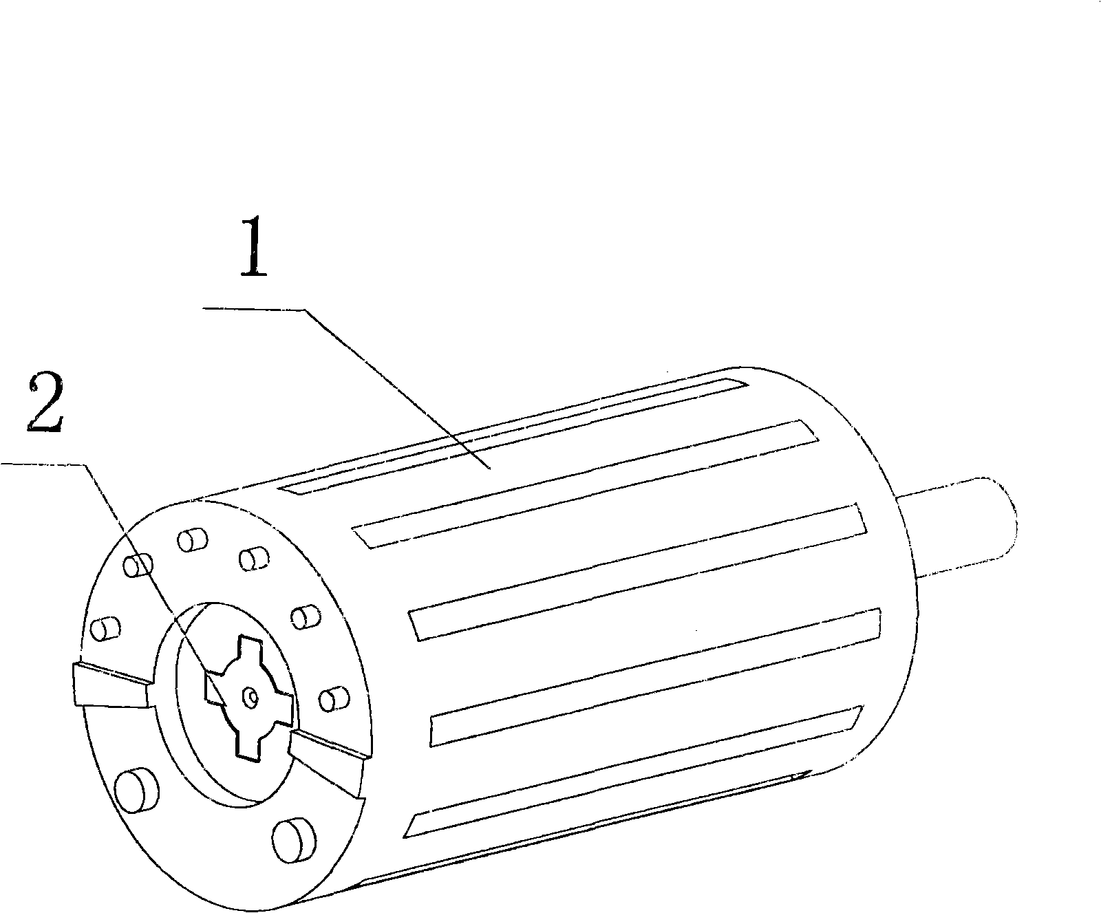
[0019] refer to image 3 As shown, the assembly structure of the crankshaft and the rotor of the present invention, wherein the inner concave stop provided on the inner edge of the shaft hole 11 of the rotor 1 is an inward concave groove 3, and the outer surface of the long axis of the crankshaft 2 is provided with a The corresponding protruding structure of the card position is the boss 4 .

[0020] refer to image 3 As shown in the assembly s...


PUM


Abstract

The invention provides an assembling structure of a crankshaft and a rotor which includes the crankshaft and the rotor; the long shaft part of the crankshaft is fixed in the shaft hole of the rotor; the invention is improved in that the inner edge of the shaft hole of the rotor is provided with more than one internal concave blocking positions; a salient structure corresponding to the blocking position is arranged on the outer side surface of the long shaft of the crankshaft; the crankshaft and the rotor are assembled into a whole by the mutual blocking of the salient structure and the internal concave blocking position; the heating working procedure is omitted, the assembling operation is simple and convenient, the fixing blocking intensity of the crankshaft and the rotor is high, the finished product rate is improved and the manufacture and assembling cost is reduced by fixing the crankshaft and the rotor by a mechanical blocking position structure.

Description

1. Technical field [0001] The invention relates to a compressor, in particular to an assembly structure of a crankshaft and a rotor, which can save procedures and improve the fixed engagement strength by improving the assembly structure of the crankshaft and the rotor. 2. Background technology [0002] A compressor is a mechanical device that can compress driving fluids such as air and refrigerant after receiving power transmitted by a power generating device such as a motor (motor) or a turbine (turbine), so that the pressure of the driving fluid raised. Such compressors are used in a wide variety of products ranging from general home appliances such as air conditioners and refrigerators to factory equipment. [0003] The above-mentioned compressors can be classified into positive displacement compressors (positive displacement compressors) and turbo compressors (dynamic compressors or turbo compressors) according to compression forms. Among them, positive displacement co...

Claims


Application Information

Patent Timeline
Patent Type & Authority Applications(China)
IPC IPC(8): F16B3/00
Inventor 付学明
Owner LG ELECTRONICS (TIANJIN) APPLIANCES CO LTD
Why Eureka
Try Eureka