Bandwidth resource saving method

A bandwidth resource and bandwidth technology, applied in the field of bandwidth resource saving, can solve the problems of inability to deploy resource reservation protocols in large numbers, complex implementation of resource reservation protocols, heavy burden on intermediate nodes, etc., to improve network availability and optimal utilization. and throughput, easy-to-achieve effects

Inactive Publication Date: 2009-02-04
ZTE CORP
View PDF0 Cites 19 Cited by
  • Summary
  • Abstract
  • Description
  • Claims
  • Application Information

AI Technical Summary

Problems solved by technology

[0011] In the current IP network, the resource reservation protocol (RSVP) can be used to realize the bandwidth reservation, availability, and priority on the network path. The resource reservation protocol is based on each flow, so that the node To retain the state information of each flow, the burden on the intermediate nodes is heavy, and each node needs to exchange a large amount of data signaling at the control plane, so the scalability is poor
And each node in the network has to maintain various databases to implement complex functional modules (such as resource reservation, routing, admission control, etc.), resulting in great complexity
Therefore, the resource reservation protocol has great limitations
In IPv6, the RSVP protocol can also be inherited as an internal application of IPv6, but the limitations of the resource reservation protocol still exist, and it is not convenient for mass deployment in IPv6 networks
[0012] For the bandwidth detection of the path in the network, the implementation of the resource reservation protocol is still complicated, and the resource reservation protocol cannot be deployed in large quantities due to limitations.

Method used


Image

  • Bandwidth resource saving method
  • Bandwidth resource saving method
  • Bandwidth resource saving method

Examples


Embodiment Construction

[0039]The core idea of ​​the present invention is: before the detection node (which can be a source node or an access device) sends traffic, through a detection mechanism, the maximum available bandwidth of the path between it and the destination node is accurately known, and according to the detection The maximum available bandwidth of , and the detection node implements a bandwidth control strategy for the corresponding traffic locally.

[0040] Below in conjunction with accompanying drawing and specific embodiment the present invention is described in further detail:

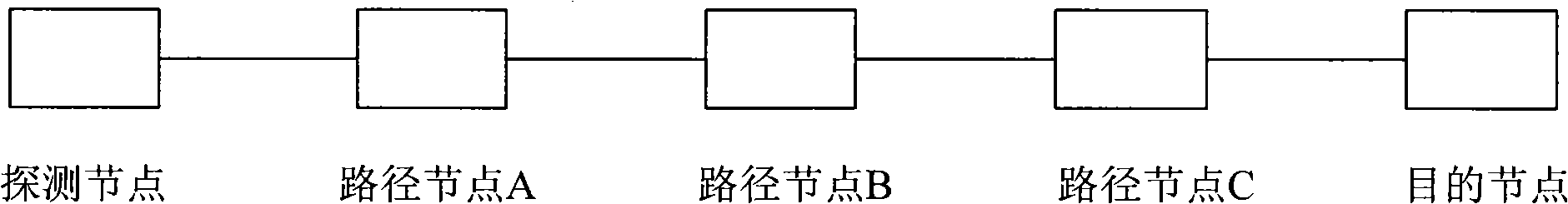
[0041] figure 1 It is a simple schematic diagram, pointing out the location and connection mode of the detection node, the intermediate node of the path and the destination node in the current IPv6 network. The detection node in the present invention may be an access device or a source node in practice.

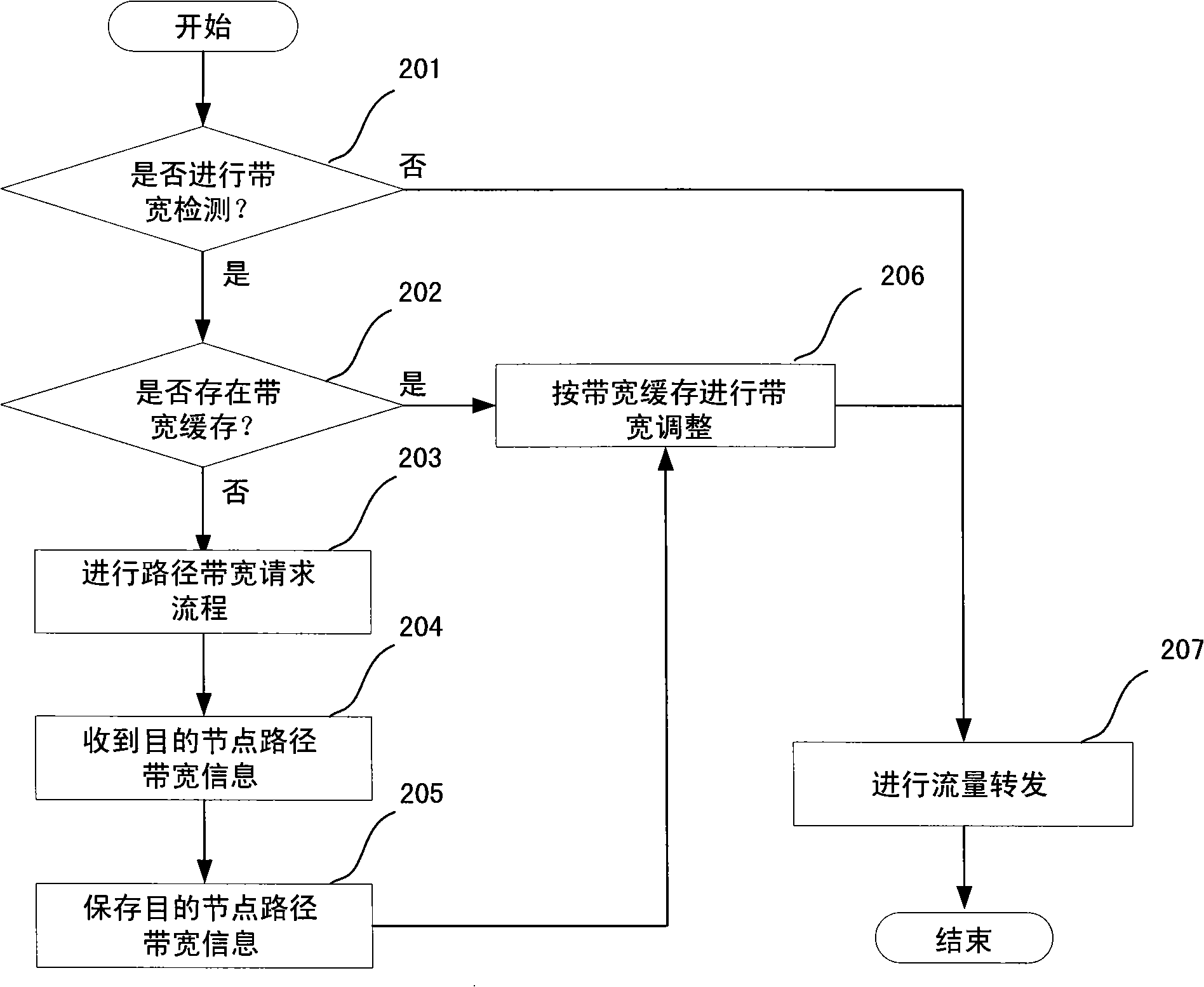
[0042] figure 2 It is the processing steps of the detection node in the process of data packet forwar...


PUM


Abstract

The invention discloses a method of saving the bandwidth resource, comprising the following: a source node or an access node constructs a path detection requesting message carrying information according to the maximum available bandwidth from a local node to the inyoite interface link of a destination node, and sends the message to a middle node on a path from the local node to the destination node; after the middle node receives the path detection requesting message, the middle node compares the maximum available bandwidth from the local node to the inyoite interface link of the destination node with that in the requesting message to replace the maximum available bandwidth value or directly forwards the maximum available bandwidth value to a next node; and after the destination node receives the path detection requesting message, the destination node constructs a path detection reversion message, carries the maximum available bandwidth in the requesting message, and sends the reversion message to the source node or the access node. The invention perceives the path bandwidth in advance, controls the flow bandwidth at the source node or the access node, and saves the bandwidth resource of the middle node, thereby making the flow on the network link reach the optimum rate of utilization and throughput and improving the availability and the safety of the network.

Description

technical field [0001] The invention relates to the technical field of network communication, in particular to a method for saving bandwidth resources. Background technique [0002] The Internet is an ever-growing computer network. When the IP protocol was first introduced, the network only needed to support the interconnection of hundreds of sites and hosts, and the 32-bit IPv4 protocol address fully met the requirements. However, with the rapid development of broadband networks, the large-scale deployment of NGN (next generation network) and 3G networks, and home networks are about to become a reality, a large number of IP addresses are needed. There is a severe shortage of widely used IPv4 addresses. Although technologies such as CIDR (Classless Intra-Domain Routing) and NAT are currently used to further delay the depletion of IPv4 addresses, IPv4 addresses will definitely be depleted in the near future. Therefore, as early as around 1990, the IETF began to research and...

Claims


Application Information

Patent Timeline
Patent Type & Authority Applications(China)
IPC IPC(8): H04L12/56H04L29/06H04L47/525
Inventor 郭金辉
Owner ZTE CORP
Why Eureka
Try Eureka