Heavy double-side land preparation device
A soil preparation machine and heavy-duty technology, which is applied to harvesters, tillage tools, crop processors, etc., can solve the problems of incomplete weight distribution of soil preparation machines, etc., and achieve the effect of reasonable and compact overall design, firm frame, and balanced weight distribution
- Summary
- Abstract
- Description
- Claims
- Application Information
AI Technical Summary
Problems solved by technology
Method used
Image
Examples
specific Embodiment approach 1
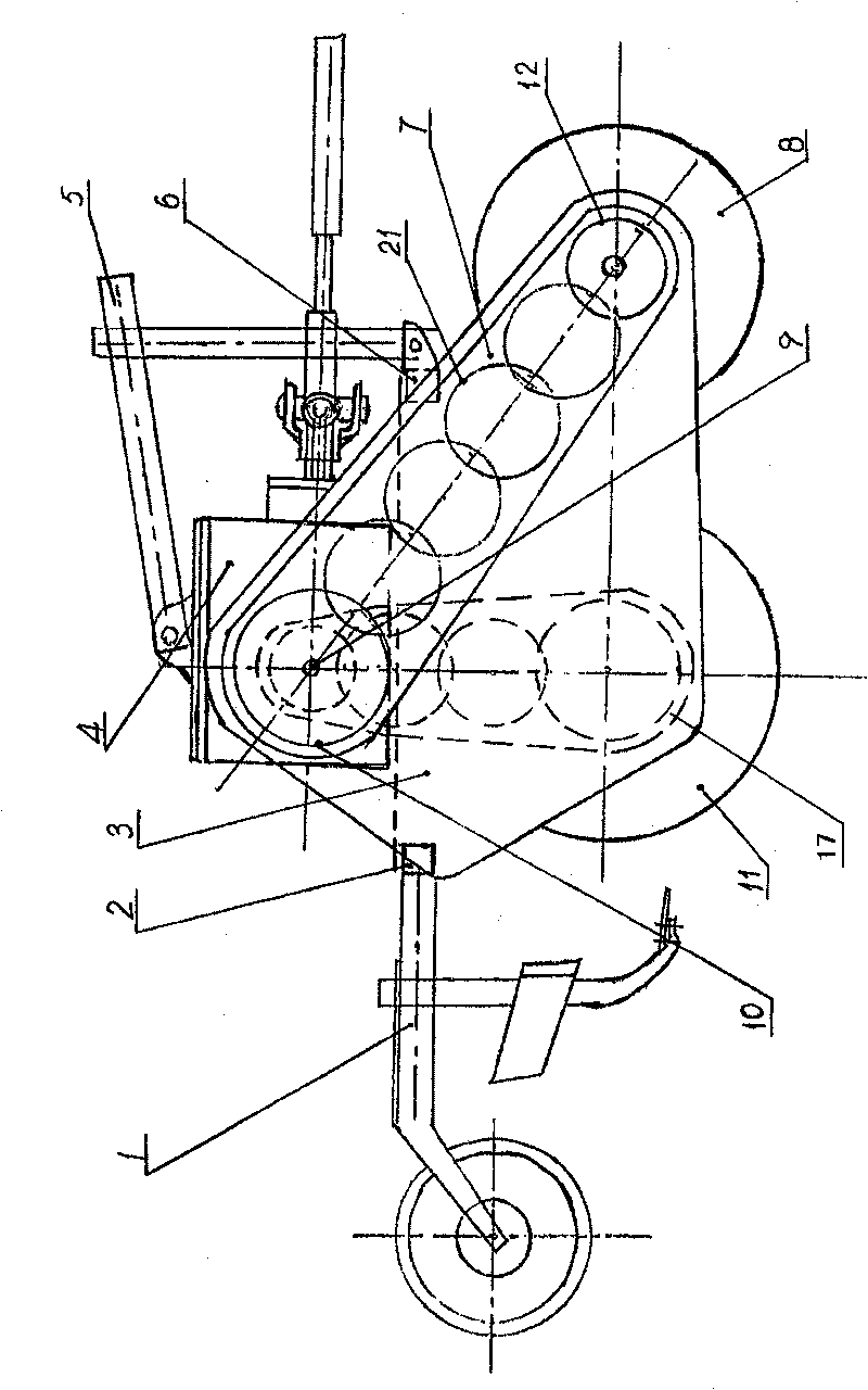
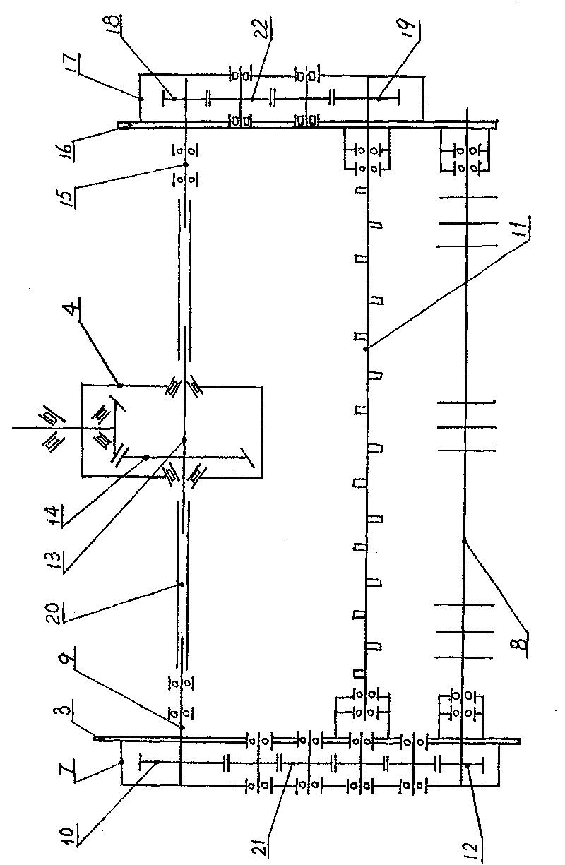
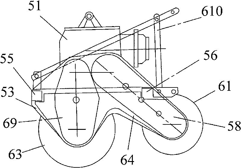
[0006] Specific implementation mode one: the following combination image 3 , Figure 4 and Figure 5 This embodiment will be specifically described. In this embodiment, the frame composed of the right side plate 53, the left side plate 54, the rear beam 55 and the front beam 56, the main transmission box 51, the middle vertical plate 64, the left stubble removal cutter shaft gearbox 57, and the right stubble removal cutter shaft gear Box 58, left rotary tiller shaft gearbox 59, right rotary tiller shaft gearbox 69, left stubble cutter shaft assembly 60, right stubble cutter shaft assembly 61, left rotary tiller shaft assembly 62, right rotary tiller shaft assembly 63, the left side rotary tillage power transmission shaft 65, the right side rotary tillage power transmission shaft 66, the left side stubble removal power transmission shaft 67 and the right side stubble removal power transmission shaft 68, the main transmission box 51 is fixed on the right side plate 53, the le...
specific Embodiment approach 2
[0008] Specific embodiment two: The difference between this embodiment and embodiment one is: the left stubble removal cutter shaft assembly 60 is connected with the middle vertical plate 64 and the left side plate 54 through bearings, and the right stubble removal cutter shaft assembly 61 is connected with the middle vertical plate 64 and the left side plate 54. The right side plate 53 is connected through bearings, the left rotary tiller shaft assembly 62 is connected with the middle vertical plate 64 and the left side plate 54 through bearings, and the right rotary tiller shaft assembly 63 is connected with the middle vertical plate 64 and the right side plate 53 through bearings .
specific Embodiment approach 3
[0009] Specific implementation mode three: the following combination Image 6 This embodiment will be specifically described. The difference between this embodiment and Embodiment 1 is: the left rotary tillage power transmission shaft 65 is composed of a middle rod 651, a left end sleeve 652 and a right end sleeve 653, the middle rod 651 is arranged between the left end sleeve 652 and the right end sleeve 653 and The three are coaxial, the left end of the No. 1 power output shaft 511 is inserted in the right end sleeve 653 and is splined, and the power input shaft 591 of the left rotary blade shaft gearbox 59 is inserted in the left end sleeve 652 and is splined. . With such arrangement, the flexibility of the middle rod 651 in the length direction can be used to reduce the influence of the possible non-concentric error of the power output shaft 511 of the No. 1 power output shaft and the power input shaft of the left-hand tiller shaft gearbox 59. The design properly reduces...
PUM
 Abstract
Description
Claims
Application Information
 - R&D
- Intellectual Property
- Life Sciences
- Materials
- Tech Scout
- Unparalleled Data Quality
- Higher Quality Content
- 60% Fewer Hallucinations
Browse by: Latest US Patents, China's latest patents, Technical Efficacy Thesaurus, Application Domain, Technology Topic, Popular Technical Reports.
© 2025 PatSnap. All rights reserved.Legal|Privacy policy|Modern Slavery Act Transparency Statement|Sitemap|About US| Contact US: help@patsnap.com


