

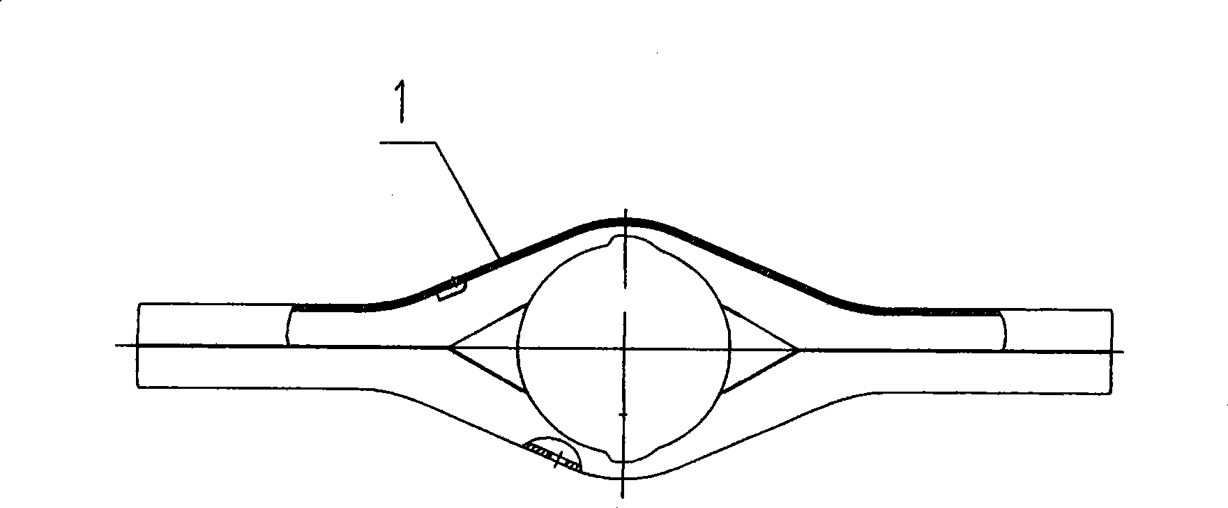
Welding device and technique of axle housing assembly Y-shaped weld joint
A welding equipment and body technology, applied in welding equipment, arc welding equipment, metal processing equipment, etc., can solve the problems of too high requirements for axle housing body assembly, failure to meet product quality requirements, and high welding labor intensity. The effect of high degree of automation, easy maintenance and convenient operation
- Summary
- Abstract
- Description
- Claims
- Application Information
AI Technical Summary
Problems solved by technology
Method used
Image

Examples
Embodiment 1
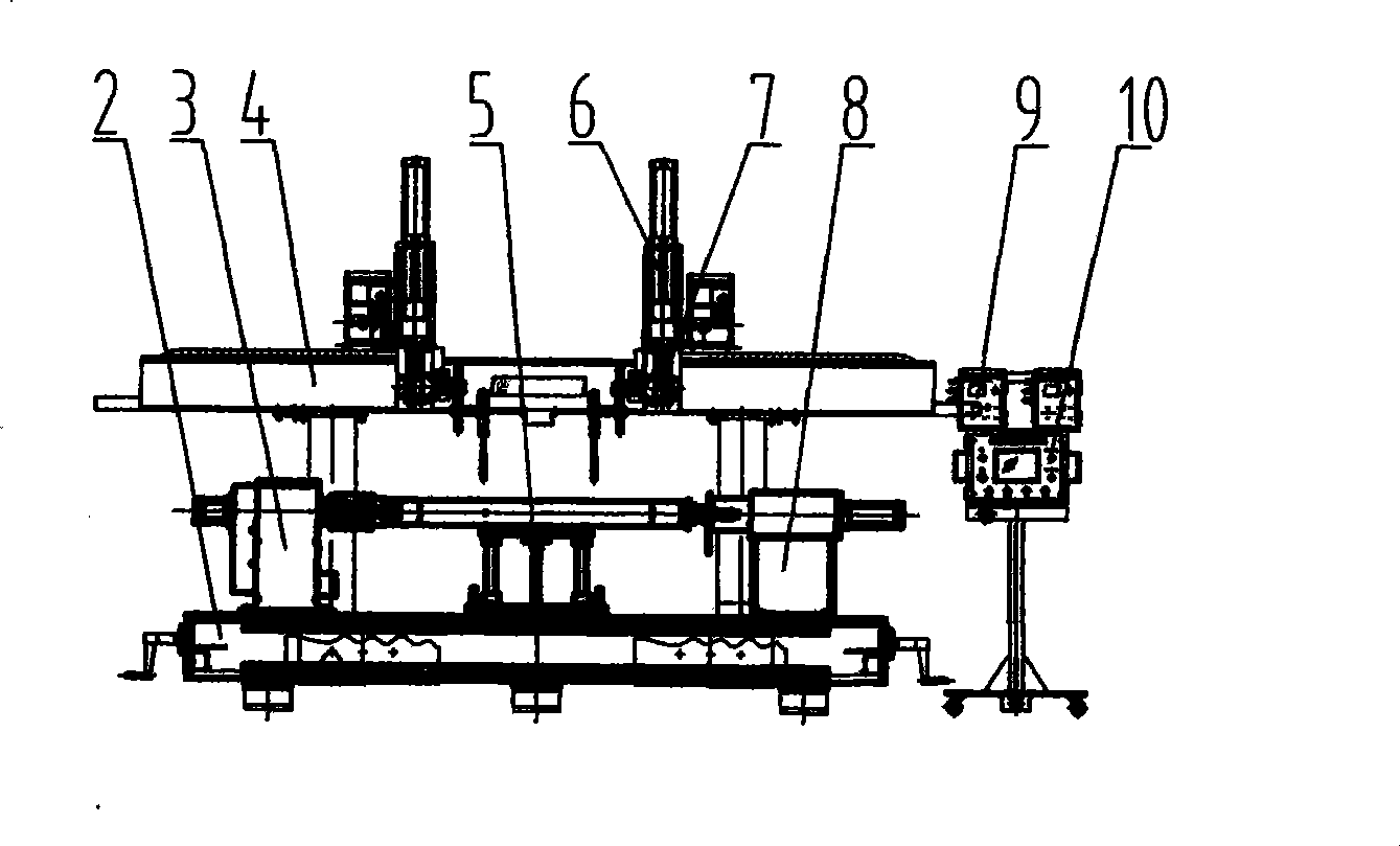
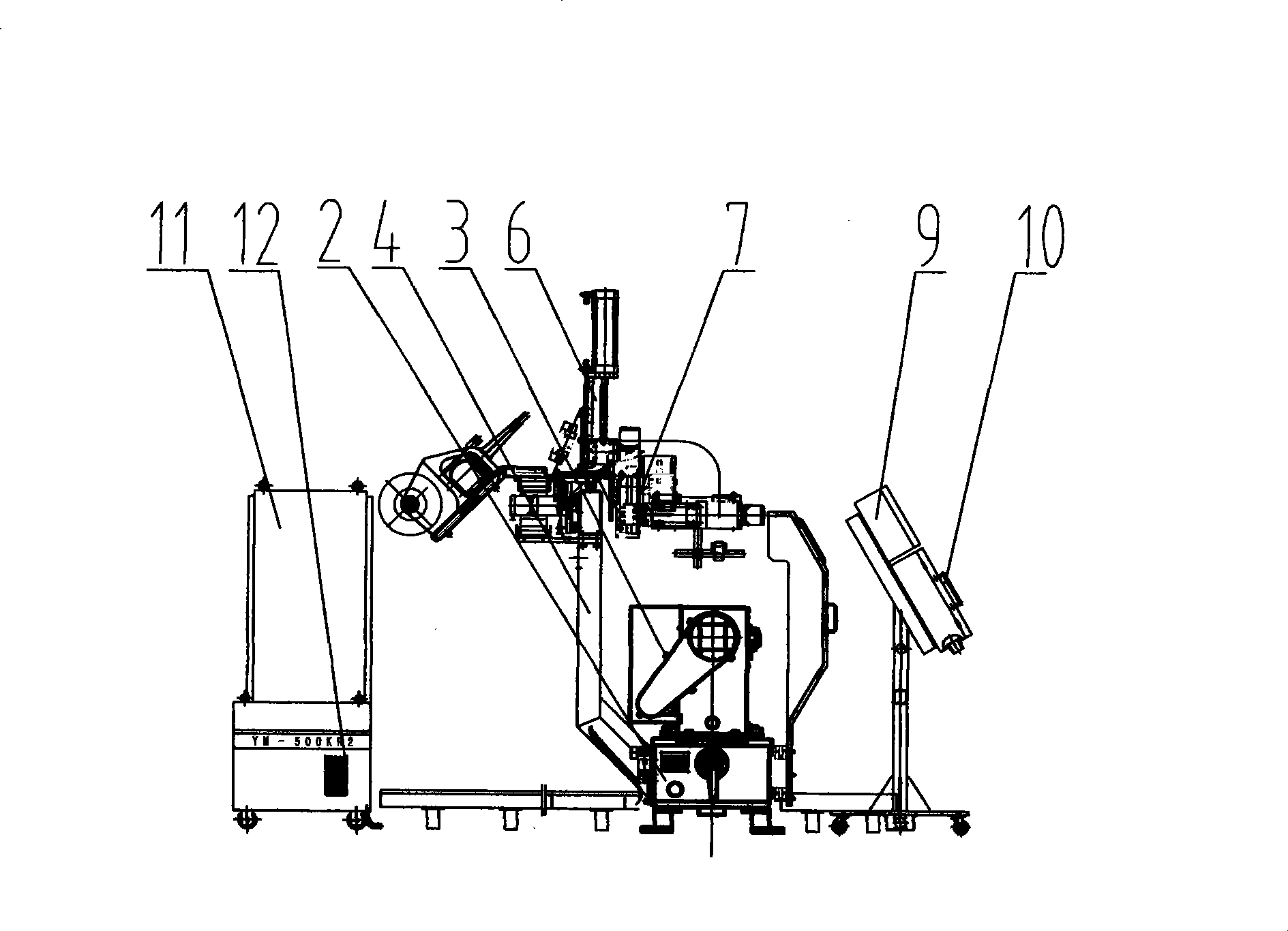
[0015] Welding equipment includes bed 2, active machine head 3, beam assembly 4, center positioning device 5, welding torch pneumatic lifting mechanism 6, welding torch adjustment mechanism 7, driven machine head 8, oscillator 9, automatic welding controller 10, electrical control System 11, welding power source 12, active machine head 3 and driven machine head 8 are connected to the two ends of the installation guide rail surface of the bed 2 through positioning keys, rotating screw rods and bolts, the active machine head 3 and driven machine head 8 are concentric, and the center The positioning device 5 is connected in the middle of the installation guide rail surface of the bed 2 through positioning keys and bolts. The center positioning device 5 is equipped with an up and down adjustment device. After the center positioning device 5 is installed, the upper length can be adjusted up and down to ensure that the workpiece is placed on the center positioning device. 5. The cent...
PUM
 Abstract
Description
Claims
Application Information