
Method and apparatus for modular embedded control system

a control system and embedded technology, applied in computer control, program control, instruments, etc., can solve the problems of time-consuming and expensive methods, and time-consuming embedded controllers and external devices, so as to save the expense of alternative mounting methods and save time in programming steps into each pi

Inactive Publication Date: 2007-08-21
SALERNO MARK
View PDF3 Cites 18 Cited by
  • Summary
  • Abstract
  • Description
  • Claims
  • Application Information

AI Technical Summary

Benefits of technology

"The present invention provides an embedded modular control system that is designed into modules. The system includes a computer and graphics display module with an external inter-integrated circuit (I2C) bus. The system can be quickly prototyped and produced by plugging in pre-made control modules that are required for a particular application. The system allows for the automatic detection and conversion of module configurations on the bus. The system also includes an infrared port for transmitting data to external handheld computers and a power supply module for additional modules. The system includes an application template for starting an application to control a piece of equipment. The system also includes a method for drawing and converting bit mapped fonts, a software driver for displaying the fonts on a graphics screen, and a digital I / O module for driving equipment. The system also includes a temperature sensor module, a motor control board, a pressure sensor board, and a custom keyboard. The technical effects of the present invention include improved efficiency, reliability, and cost-effectiveness for embedded control systems."

Problems solved by technology

However, this method is time consuming and expensive.
These embedded controllers and external devices are time consuming to program.
This method is time consuming and expensive.
These computers do not contain all the components to control the equipment, such as displays, keyboards, or high-level electromechanical drivers.
These systems do not handle real-time applications very well and are expensive and require extensive programming.
The user would then go to multiple sites and send the recipe data to other devices, which would save a considerable amount of time.

Method used


Image

  • Method and apparatus for modular embedded control system
  • Method and apparatus for modular embedded control system
  • Method and apparatus for modular embedded control system

Examples


Embodiment Construction

Top Level Description of Modular Embedded Control System

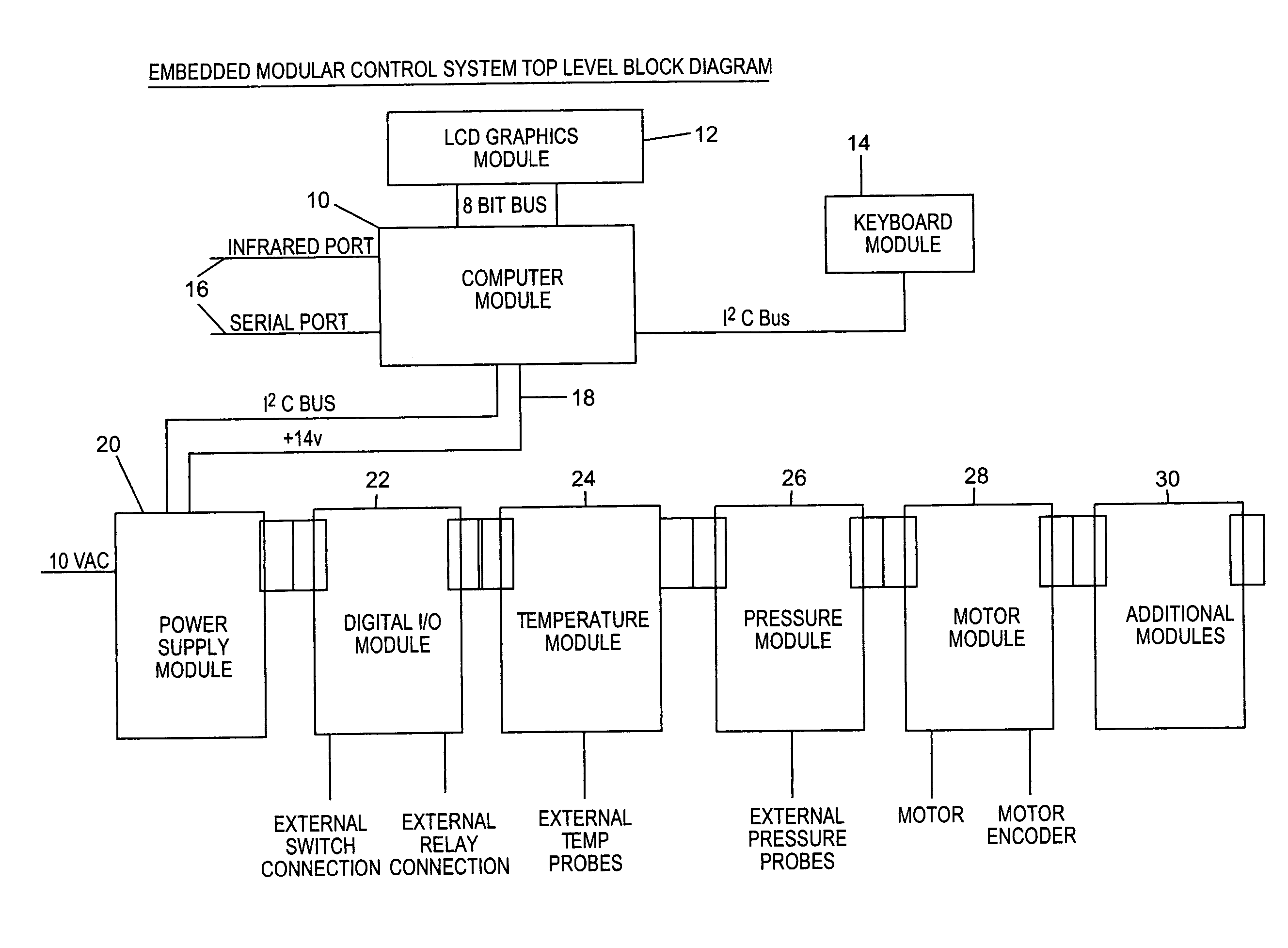
[0051]FIG. 1 shows a top-level block diagram of a modular embedded control system formed in accordance with the present invention for use in controlling, for instance, an oven for preparing food. The apparatus includes electronic modules that connect together to form a control system. A computer module 10 is the heart of the system. A graphics module 12 is preferably an industry standard device that is connected to the computer module 10 via an 8-bit bus with power. A standard or custom keyboard module 14 is preferably connected to the computer module 10 via an I2C bus. External infrared and serial ports 16 are preferably used for communication to external computers. External I / O modules 20, 22, 24, 26, 28, 30 are preferably connected via a cable that includes an I2C bus and a +14 volt power supply signal.

[0052]External modules 20, 22, 24, 26, 28, 30 preferably include printed circuit boards that connect together and form a pow...


PUM


Abstract

An embedded control system is provided, which includes a generically applicable computer module, display module, keyboard module, power supply module, and at least one input / output module. The display module is coupled to the computer module by a first communication bus, and the keyboard module is coupled to the computer module by a second communication bus. The power supply module is coupled to the computer module by a third communication bus, and the at least one input / output module is coupled to the power supply module and the third communication bus. The input / output module is adapted for coupling at least one additional input / output module to the third communication bus. The computer module automatically identifies the input / output modules on the third communication bus in response to applying power to the embedded control system. The system is adapted for different applications using software resident in the computer module.

Description

CROSS-REFERENCE TO RELATED APPLICATION[0001]This application claims the benefit of U.S. Provisional Patent Application No. 60 / 296,597 filed Jun. 7, 2001, the disclosure of which is incorporated herein by reference.BACKGROUND OF THE INVENTION[0002]1. Field of the Invention[0003]This invention relates generally to embedded controllers with integrated operator display, control, and electromechanical input / output connections and more specifically relates to electronic modules that are plugged together with an operating system and device drivers to quickly develop and produce control systems.[0004]2. Description of the Prior Art[0005]In much of the equipment today, small microcomputers called embedded controllers are used to perform various functions, such as operator input / output display, control of functions, and input / output connections to electromechanical devices. Currently, many of these devices are custom designed for each application. However, this method is time consuming and ex...

Claims


Application Information

Patent Timeline
Patent Type & Authority Patents(United States)
IPC IPC(8): H01H47/00G05B19/042G06FG06F3/00H02H9/00
CPCG05B19/0423G05B2219/21081
Inventor SALERNO, MARK
Owner SALERNO MARK
Learn More