Labyrinth type oil-gas separating structure in cover of engine spiracular atrium

An engine valve, oil-vapor separation technology, applied in the direction of engine components, machines/engines, mechanical equipment, etc., can solve problems such as damage to the crankcase seal, reduced oil performance, increased deterioration, etc., to achieve reliable work performance and easy process. Effect

Inactive Publication Date: 2009-02-11
CHERY AUTOMOBILE CO LTD
View PDF0 Cites 17 Cited by
  • Summary
  • Abstract
  • Description
  • Claims
  • Application Information

AI Technical Summary

Problems solved by technology

This will dilute the engine oil, reduce the performance of the engine oil, accelerate the oxidation, deterioration and increase consumption of the engine oil; at the same time, the water vapor will condense in the engine oil, which will form sludge and block the oil circuit; the acidic gas mixed into the lubrication system will cause damage to the engine parts Corrosion and accelerated wear; blow-by gas will also make the pressure of the crankcase too high and damage the seal of t

Method used


Image

  • Labyrinth type oil-gas separating structure in cover of engine spiracular atrium
  • Labyrinth type oil-gas separating structure in cover of engine spiracular atrium

Examples


Embodiment Construction

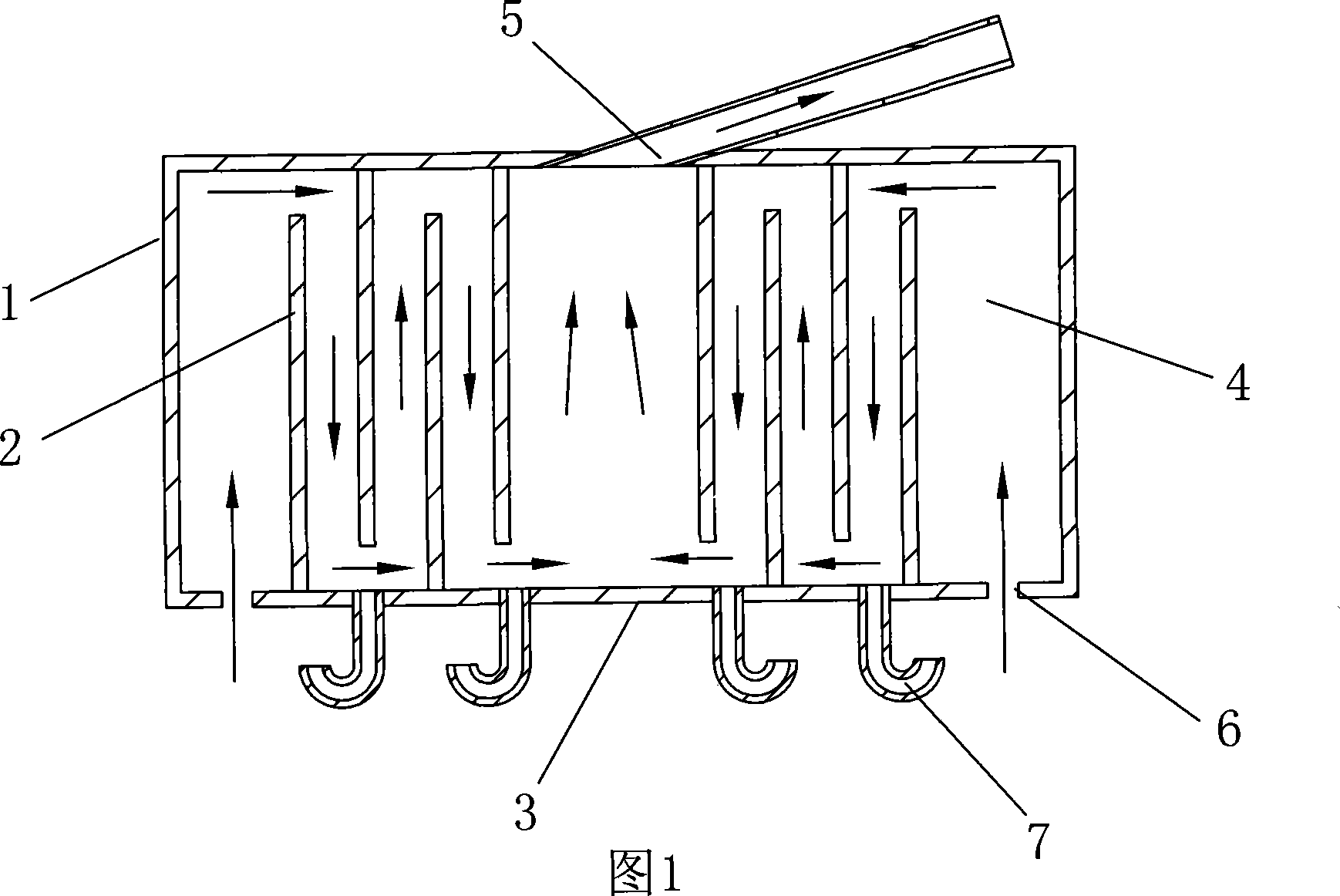
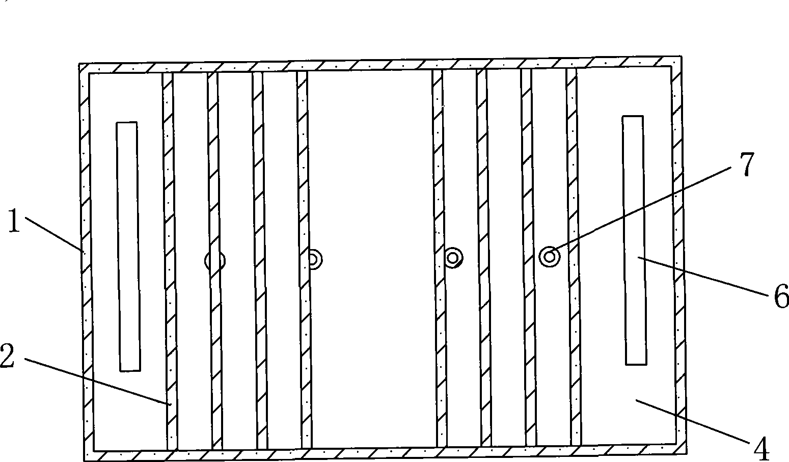
[0021] Referring to Fig. 1, in the oil-air separation chamber 4 with the mixed gas inlet 6 and the ventilation pipe outlet 5, which is composed of the oil retaining bottom plate 3 and the valve chamber cover 1, the residence time of the mixed gas in the oil-gas separation chamber 4 can be prolonged, A labyrinth structure that increases the contact area between the mixed gas and the inner wall of the oil-gas separation chamber 4.

[0022] The corresponding structural setup in a concrete implementation could be:

[0023] In the labyrinth structure, a plurality of blocking baffles 2 are arranged in the oil-gas separation chamber 4 , and the positions of the gas flow channels formed between adjacent blocking baffles 2 and the inner walls of the oil-gas separation chamber 4 are staggered.

[0024] In the labyrinth structure formed in the oil-gas separation chamber 4 by the multi-channel baffle plate 2, the flow direction of the mixed gas is zigzag.

[0025] The gas mixture inlet 6...


PUM


Abstract

The invention relates to a labyrinth gas-oil separating structure in a valve cover of an engine and is characterized in that: a gas-oil separating chamber, which is jointly composed by an oil baffle base plate and the valve cover and is provided with a gas mixture inlet and an outlet of a ventilating pipe, is internally provided with a labyrinth structure which can prolong the detention time of the gas mixture in the gas-oil separating chamber and enlarge the contact area between the gas mixture and the inner wall of the separating chamber. The labyrinth gas-oil separating structure aims at simplifying the arrangement of a ventilating system and optimizing and modifying the structures of the valve cover and the oil baffle plate, thus forming an effective oil separating labyrinth and achieving the effect of independent arrangement of a gas-oil separating device; and the whole ventilating system of the engine becomes simpler and more effective.

Description

technical field [0001] The invention relates to an automobile engine ventilation system, more specifically to the arrangement of an oil-vapor separation structure in the automobile engine ventilation system. Background technique [0002] When the automobile engine is running, the high-pressure combustible mixture and burned gas in the combustion chamber will more or less enter the crankcase through the gap between the piston assembly and the cylinder, causing blow-by. The components of blow-by gas are unburned hydrocarbons, water vapor and exhaust gas. This will dilute the engine oil, reduce the performance of the engine oil, accelerate the oxidation, deterioration and increase consumption of the engine oil; at the same time, the water vapor will condense in the engine oil, which will form sludge and block the oil circuit; the acidic gas mixed into the lubrication system will lead to damage to the engine parts Corrosion and accelerated wear; Blow-by gas will also make the p...

Claims


Application Information

Patent Timeline
IPC IPC(8): F01M13/04
Inventor 方勇王华进吕碧波
Owner CHERY AUTOMOBILE CO LTD
Why Eureka
Try Eureka