Glue-sizing double R groove shaped conductive thread expanding pulley

A pay-off pulley and groove-shaped technology, which is applied in the field of overhead power transmission line tension stringing construction equipment, can solve the problem of reducing the contact area between the wire and the wire pay-off pulley groove, wire wear and tear, wire pay-off pulley structure deformation, and reduction of discharge. The service life of wire pulleys and other issues can be improved to improve safety and wire efficiency, save engineering expenses, and reduce corona loss.

Active Publication Date: 2009-02-11
CHINA ELECTRIC POWER RES INST
View PDF0 Cites 7 Cited by
  • Summary
  • Abstract
  • Description
  • Claims
  • Application Information

AI Technical Summary

Problems solved by technology

At present, the wire pay-off pulleys in the widely used pay-off pulleys are all single-groove pulleys. Since the radius of the connecting pipe protection device is more than twice the radius of the wire, in order to make both wires pass through the wire pay-off pulley smoothly, a single The radius of the wheel groove of the wire pay-off pulley must be slightly larger than the radius of the connecting pipe protection device, so that the radius of the wire and the radius of the wire pay-off pulley have a large difference, reducing the distance between the wire and the wire pay-off pulley. contact area, which will cause greater wear and tear on the wires and cause structural deformation of the wire pay-off pulley, and even cause irreversible loose strands of the wires, which will eventually lead to serious corona loss, environmental noise and radio interference on the running line.
[0004] In order to make the pulley not only protect the wire, but also not easy to be damaged during construction, if the glue-hanging layer covers the wheel groove and extends to the outside of the wheel rim, due to the harsh working conditions at the pay-out construction site, the wire pay-off pulley and other hard The high-quality materials are often extruded and collided, or transported in the absence of transportation channels in high mountains and ridges, etc., causing the adhesive layer to open and fall off, causing the wire pay-off pulley to be scrapped, which seriously reduces the overall service life of the pay-off tackle, thus Increased construction cost and extended construction period due to replacement of pay-off block

Method used


Image

  • Glue-sizing double R groove shaped conductive thread expanding pulley
  • Glue-sizing double R groove shaped conductive thread expanding pulley
  • Glue-sizing double R groove shaped conductive thread expanding pulley

Examples


Embodiment Construction

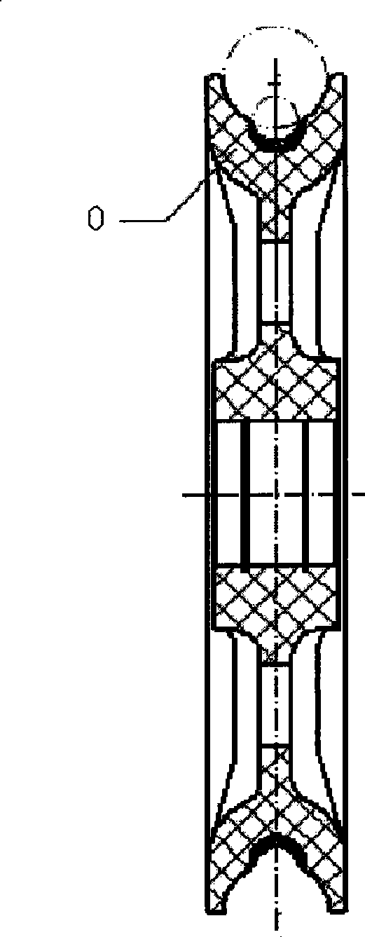
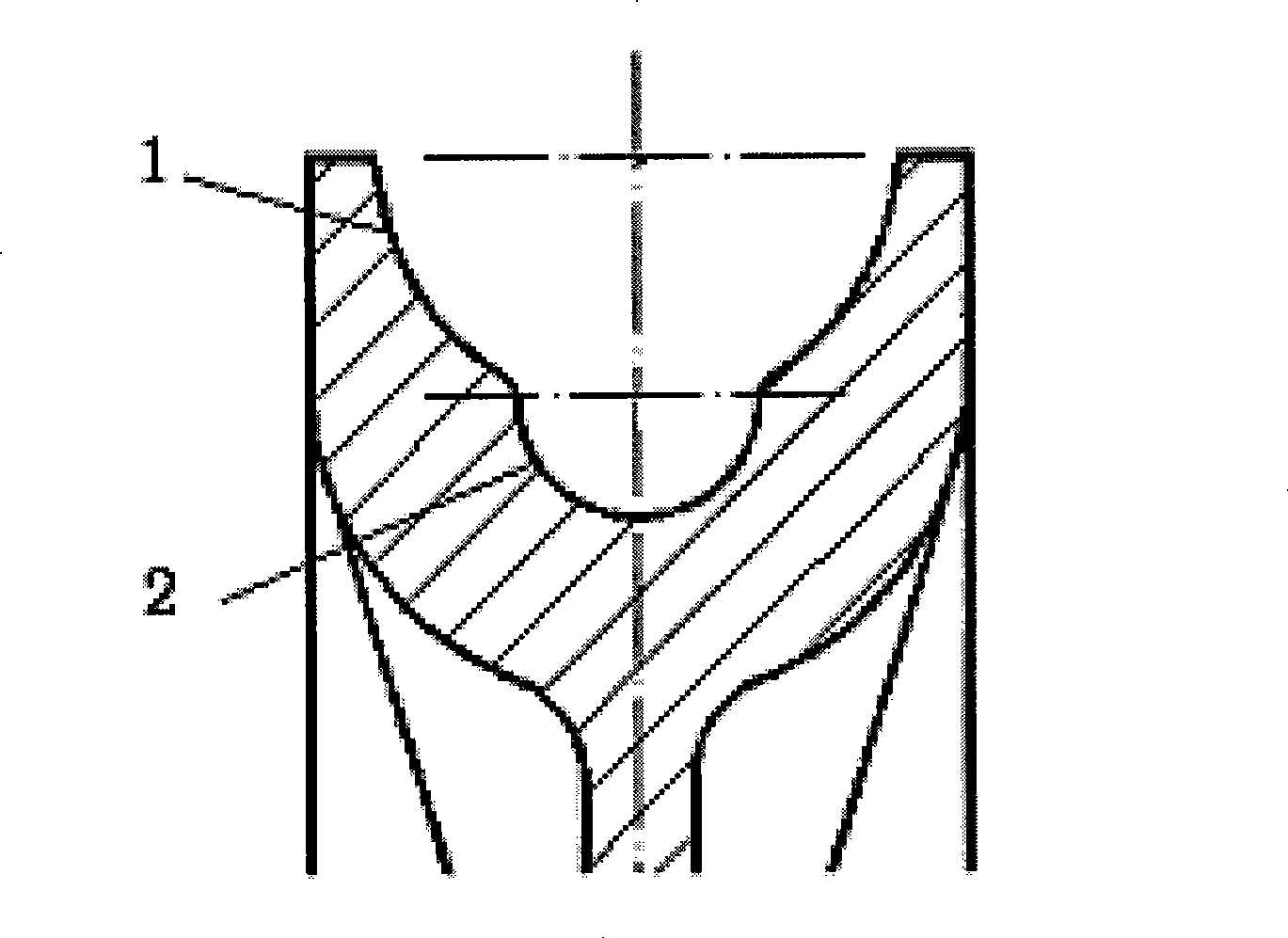
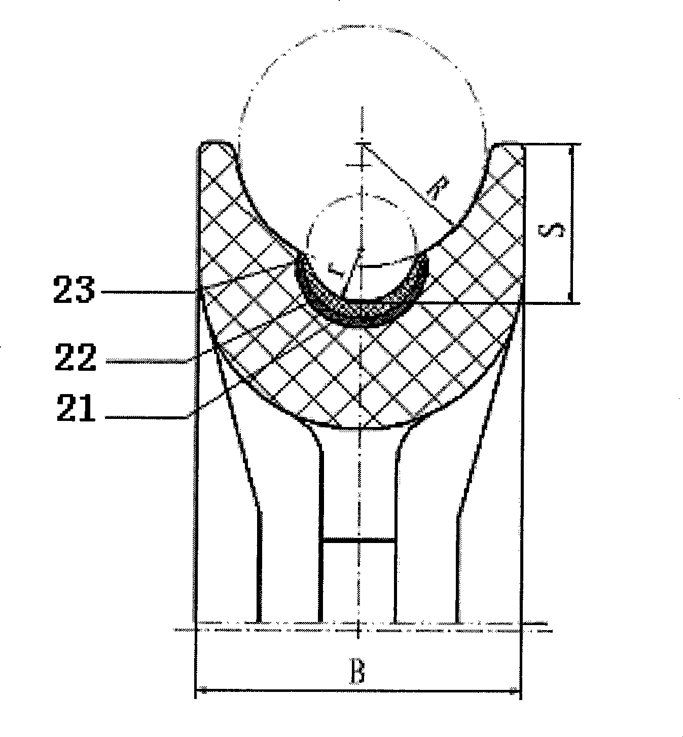
[0023] figure 1 Shown is the general structure schematic diagram of the double R groove shape wire pay-off pulley of the present invention, the wheel groove of the pulley body of the wire pay-off pulley on it adopts the double R groove shape of hanging glue, promptly is made up of two circular arc grooves 1, 1 and 2. 2, a smaller radius arc groove 2 is set at the bottom of the larger radius arc groove 1; also for the purpose of protecting the wire, the connection between the large and small arcs 1 and 2 has a chamfer. A glue-hanging layer 22 is provided on at least the inner surface of the arc groove with a smaller radius. The thickness of the pay-off pulley is B, and the total depth of the wheel groove is S. The large and small arc radii R and r after gluing are matched with the radii of the splicing tube protection device and the wire respectively, image 3 It is a schematic diagram of the first glue-hanging method of the wire pay-off pulley, Figure 4 It is a schematic d...


PUM


Abstract

The invention relates to a cementing double-R groove-shaped lead stringing pulley with a double-R groove-shaped pulley groove selection, which is composed of two types of circular arc with different radii. One circular-arc-shaped groove with a short radius is formed at the bottom of the arc-shaped groove with a large radius and a cementing layer is arranged on at least the internal surface of the arc-shaped groove with small radius. Cementing plays a certain role in protecting the lead. The service life of the lead stringing pulley is prolonged. The radii of the big and the small circular arcs are respectively matched with the radii of a connecting pipe protecting device and the lead, thereby enlarging the contact area between the lead and the pulley groove of the lead stringing pulley when the lead passes through a connecting pipe protecting device, and reducing the wear of the lead. At the same time, the small arc-shaped groove has a depth enough to avoid construction accident caused by the lead which leaves out of the pulley groove of the pulley during the stringing process. Therefore, the lead stringing pulley has the advantages that the wear of the lead is reduced, the service life of the lead stringing pulley is prolonged, the safety of stringing construction is improved and the maintenance cost of engineering is reduced.

Description

technical field [0001] The invention belongs to the field of equipment for tension stringing construction of overhead power transmission lines, and in particular relates to the main part of a wire pay-off pulley—a wire pay-off pulley. Background technique [0002] In the tension stringing construction of overhead transmission lines, it is generally necessary to deploy 6-8km (Technical Guidelines for Tension Stringing Construction of 1000kV Overhead Transmission Lines, hereinafter referred to as "Technical Guidelines") conductors at one time, and the special terrain will exceed the standard. The length of the wire section, according to the production length of each shaft wire, needs to be connected several times with the splicing pipe. Since the crimped splicing pipe cannot be bent and deformed during construction, a special splicing pipe is usually installed on the splicing pipe to protect the wire when the wire is unwound. device. According to the "Technical Guidelines", 2...

Claims


Application Information

Patent Timeline
Patent Type & Authority Applications(China)
IPC IPC(8): H02G1/02
Inventor 裘雅萍夏拥军缪谦温超
Owner CHINA ELECTRIC POWER RES INST
Why Eureka
Try Eureka