Apparatus and method processing material by ultrasonic apparatus

An ultrasonic and ultrasonic welding technology, which is applied in chemical instruments and methods, lamination devices, and layered product processing, can solve problems such as energy loss and achieve low shear force and small wear

Inactive Publication Date: 2009-02-11
SCA HYGIENE PROD AB
View PDF1 Cites 16 Cited by
  • Summary
  • Abstract
  • Description
  • Claims
  • Application Information

AI Technical Summary

Problems solved by technology

The deviation between the actual welding power and the theoretically expected welding power can be explained by the above-mentioned phenomenon of friction and mechanical compression, that is, as a result of the compression of the laminate before the ultrasonic device, the gradual accumulation of uncontrollable effects, and Energy is lost as a result of the mechanical compression of the material

Method used


Image

  • Apparatus and method processing material by ultrasonic apparatus
  • Apparatus and method processing material by ultrasonic apparatus
  • Apparatus and method processing material by ultrasonic apparatus

Examples


Embodiment Construction

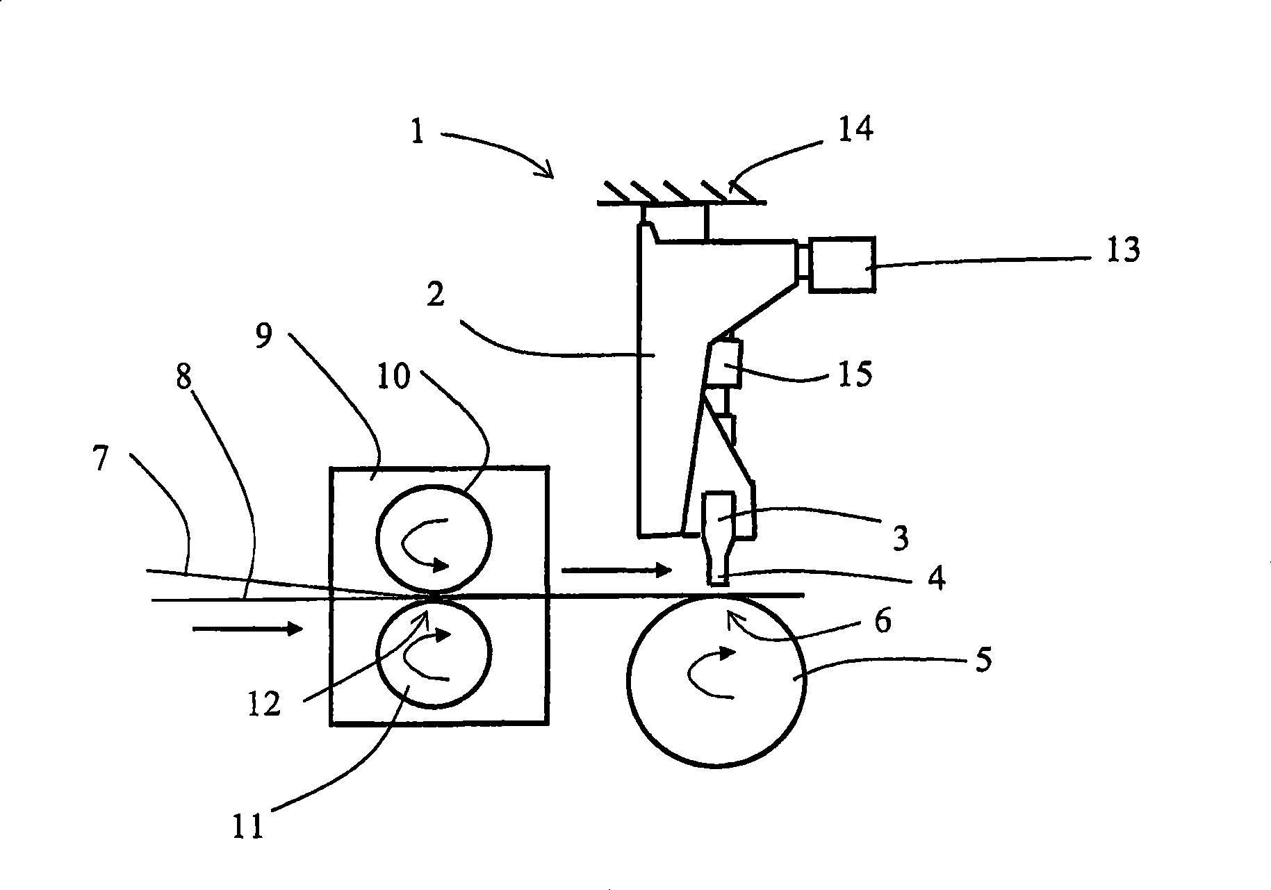
[0022] figure 1 is a schematic side view of an apparatus 1 for sonication, wherein the apparatus is used in connection with the present invention. More specifically, according to the prior art, the device 1 comprises an ultrasonic device 2 with a sonotrode 3 implemented with a contact device 4 , namely an end piece.

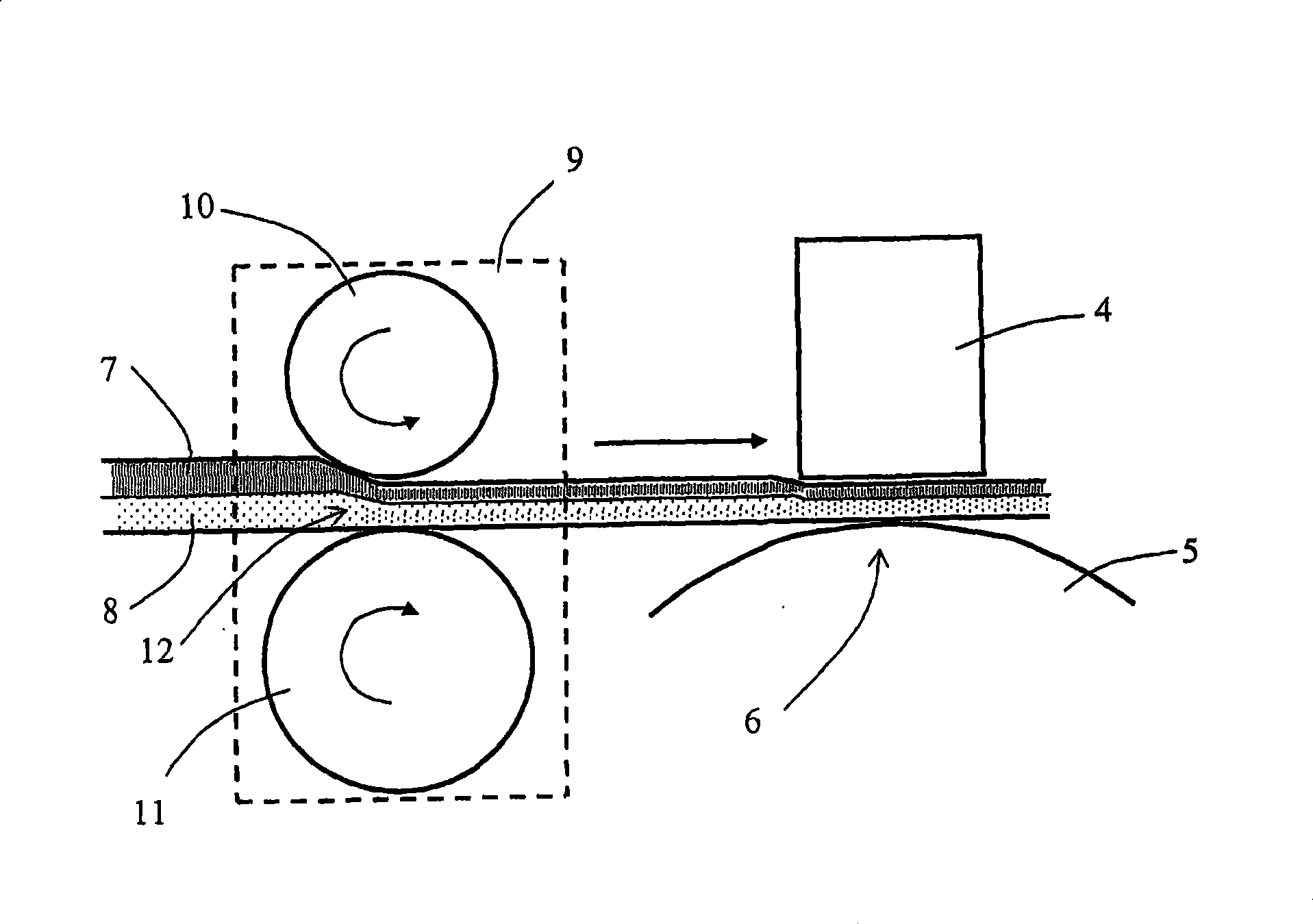
[0023] pass figure 1 It will be appreciated that the ultrasonic device 2 is arranged in close proximity to a rotating abutment roller 5, the periphery of which roller 5 defines an abutment surface. The backup roll 5 is also suitably provided with a pattern for the ultrasonic treatment in question. The contact device 4 of the sonotrode 3 also faces the material and is arranged at a small distance from the outer circumference of the backup roll 5 . A small gap 6 is formed in this way, that is to say a relatively small distance is formed between the contact device 4 and the outer peripheral surface of the support roller 5 . A laminate consisting of two material ...


PUM


Abstract

The present invention relates to an arrangement (1 ) for processing of a material (7, 8) comprising at least one layer of material by means of an ultrasonic device (2) consisting of an ultrasound horn (3) arranged adjacent to an abutment (5; 5'), in conjunction with which a gap is defined between the aforementioned ultrasound horn (3) and the aforementioned abutment (5; 51), in conjunction with which the aforementioned ultrasonic device (2) is arranged for the purpose of feeding the aforementioned material (7, 8) through the aforementioned gap (6). In accordance with the invention, the arrangement (1 ) includes a pre-compression unit (9; 9') for the mechanical compression of the aforementioned material (7, 8) before it is fed through the aforementioned gap (6). The invention also relates to a method for processing of the aforementioned kind.

Description

technical field [0001] The invention relates to a device for the treatment of a material comprising at least one layer of material by means of ultrasonic means, wherein said ultrasonic means comprises a sonotrode (horn) arranged in the vicinity of a support and between said sonotrode and said support A gap is defined and the purpose of the aforementioned ultrasonic means is to feed the aforementioned material through the aforementioned gap. [0002] The invention also relates to a method of processing a material comprising at least one layer of material by means of an ultrasonic device, wherein said ultrasonic device comprises a sonotrode arranged adjacent to a support, and the aforementioned method comprises feeding the aforementioned material through the aforementioned The gap between the sonotrode and the aforementioned support. Background technique [0003] Ultrasonic technology is used in specific processes for treating continuous webs of material. This technique is c...

Claims


Application Information

Patent Timeline
Patent Type & Authority Applications(China)
IPC IPC(8): B29C65/08B32B37/06B32B38/00A61F13/15
CPCB29C65/08B29C66/0222A61F2013/53991B29C66/83411A61F13/15707B32B2305/20B29C65/086B29C66/81433B29K2105/0854B29K2023/00B29L2031/4878B32B38/0012B29K2105/04B29L2009/00B32B2310/028B29K2101/12B29K2023/12B29K2023/06B29C66/92B29C65/02B29C66/92611B29C66/83415B29C66/21A61F13/15739B29C66/022B32B37/00B29K2077/00B29K2223/00B29K2067/00B29C66/8242B29C66/83413B29C65/56B29C66/1122B29C66/71B29C66/727B29C66/7294B29C66/73521B29C66/73921B29C66/9221B29C66/92445B29K2023/04B29K2023/10
Inventor M·莱赫托
Owner SCA HYGIENE PROD AB
Why Eureka
Try Eureka