Eureka AIR delivers breakthrough ideas for toughest innovation challenges, trusted by R&D personnel around the world.

Water pump impeller

A technology of water pump impeller and impeller, applied in the field of water pump impeller, can solve the problems of difficult adjustment, poor cooling, low efficiency, etc., and achieve the effects of reducing installation clearance, improving pumping efficiency, and improving cooling effect

Active Publication Date: 2010-06-02
安庆福莱克斯动力科技有限公司
View PDF6 Cites 2 Cited by
  • Summary
  • Abstract
  • Description
  • Claims
  • Application Information

AI Technical Summary

Problems solved by technology

The prominent problems existing in the existing centrifugal pumps are low efficiency and high energy consumption
Among them, the impeller of the centrifugal pump is composed of a wheel seat and a wheel shaft, and the impeller composed of a single-layer spiral water-repelling blade is evenly distributed around the wheel seat. The angle setting of the water blade is not reasonable enough; and the gap between the impeller and the volute has a great relationship when it is arranged on the engine
[0004] At present, the cooling performance of the engine installed with the open impeller water pump is not good, so the emission requirements are not up to standard. In addition, the gap between the impeller of the water pump and the volute of the engine is difficult to adjust to the best, thereby reducing the pumping efficiency of the water pump.
[0005] The above two aspects have always plagued water pump manufacturers and engine manufacturers, and so far there is no good solution

Method used


Image

  • Water pump impeller
  • Water pump impeller
  • Water pump impeller

Examples


Embodiment 1

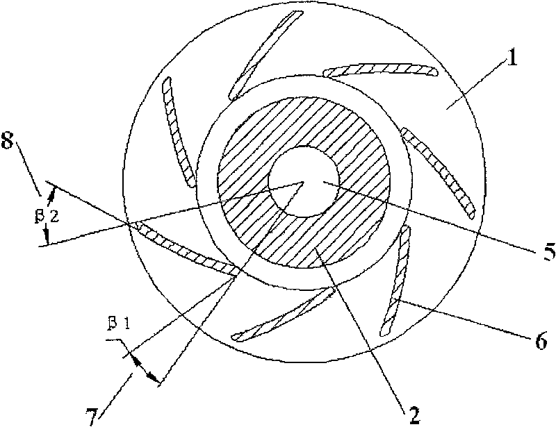
[0045] The β1 is 17°-19°; the β2 is 40°-44°.

[0046] Examples of possible combinations are:

[0047] β1=17°, β2=44°;

[0048] β1=17°, β2=40°;

[0049] β1=17°, β2=42°;

[0050] β1=19°, β2=42°;

[0051] β1=18°, β2=44°;

[0052] β1=18°, β2=40°;

[0053] β1=18°, β2=42°

[0054] β1=19°, β2=40°;

[0055] β1 = 19°, β2 = 44°; and so on.

[0056] When selecting, determine the values ​​of β1 and β2 according to actual needs.

Embodiment 2

[0058] Furthermore, the β1 is 18°; the β2 is 42°. This is an optimal option, which can be adapted to applications under different conditions.

Embodiment 3

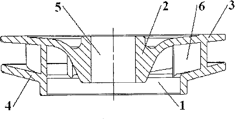
[0060] The water pump impeller 1 of the present invention is provided with an impeller front baffle 3 and an impeller rear baffle 4, and the shape of the impeller front baffle 3 and the impeller rear baffle 4 is an approximate disc shape coaxial with the water pump impeller 1 ; The blades 6 are located on the axial front and back sides of the water pump impeller 1, and are respectively connected with the impeller front baffle 3 and the impeller rear baffle 4 as a whole.

[0061] This embodiment is to change the form of the impeller from the open structure in the prior art, so that the blades of the water pump are distributed between the two baffles, so that the clearance requirements between the impeller of the water pump and the volute are not so strict, reducing the The installation clearance between the pump and the volute; this form is calculated by a formula. The distance between the impeller of the water pump and the volute has little effect on the water pumping capacity...


PUM


Abstract

The invention discloses a water pump impeller which comprises a vane inlet angle (7) Beta 1 and a vane outlet angle (8) Beta 2; the range of Beta 1 is 10 degrees to 20 degrees; the Beta 2 is 25 degrees to 45 degrees. When the technical proposal is adopted, each vane adopts the most reasonable vane inlet angle and the vane outlet angle to improve the pump water efficiency of the cooling water and the cooling effect on the engine; a front retaining plate and a back retaining plate are arranged on the impeller to enable the impeller to be fully-closed type, so as to reduce the mounting gap between the water pump and the turbine shell; the proper number of vanes is adopted to further improve the work efficiency of the water pump; the impeller is made of engineering plastic for reducing the weight of the water pump.

Description

technical field [0001] The invention belongs to the technical field of automobile structure, and relates to an automobile engine system cooling system, more specifically, the invention relates to a water pump impeller used for automobile engine cooling. Background technique [0002] Centrifugal pump is a general-purpose water pump, which is widely used in various fields of national economy, especially in the field of engines. [0003] The impeller is the heart of the centrifugal pump, and its performance directly affects the efficiency of the centrifugal pump. The prominent problems existing in the existing centrifugal pumps are low efficiency and high energy consumption. Among them, the impeller of the centrifugal pump is composed of a wheel seat and a wheel shaft, and the impeller composed of a single-layer spiral water-repelling blade is evenly distributed around the wheel seat. The angle setting of the water blade is not reasonable enough; and the gap between the impel...

Claims


Application Information

Patent Timeline
Patent Type & Authority Patents(China)
IPC IPC(8): F04D29/24F04D29/22F01P5/10
Inventor 赵前进
Owner 安庆福莱克斯动力科技有限公司
Why Eureka
Eureka Blog
Learn More