Supercharge Your Innovation With Domain-Expert AI Agents!

Multi-frequency antenna

A multi-frequency antenna and antenna technology, applied in the direction of antenna, independent non-interaction antenna combination, radiation element structure, etc., can solve the problems that it is difficult to adapt to the development trend of antenna miniaturization, the overall height of the antenna is high, and the antenna volume is large.

Inactive Publication Date: 2009-02-18
FOXCONN (KUNSHAN) COMPUTER CONNECTOR CO LTD +1
View PDF1 Cites 6 Cited by
  • Summary
  • Abstract
  • Description
  • Claims
  • Application Information

AI Technical Summary

Problems solved by technology

However, the conductive pin of the antenna adopts a three-stage structure, the structure is relatively complex, and the antenna is relatively large in size, and the overall height of the antenna is high, so it is difficult to adapt to the development trend of antenna miniaturization.

Method used


Image

  • Multi-frequency antenna
  • Multi-frequency antenna
  • Multi-frequency antenna

Examples


Embodiment Construction

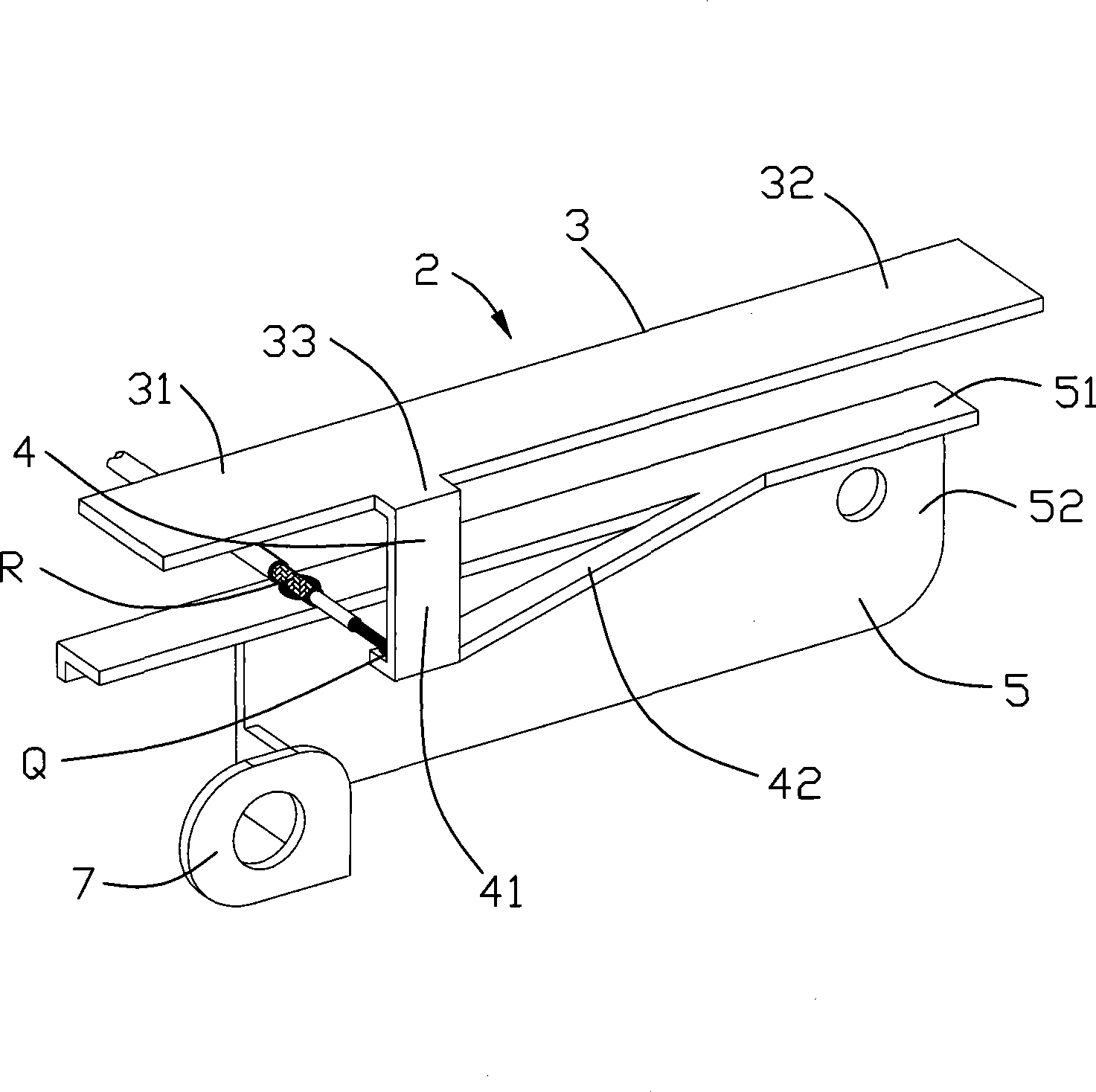
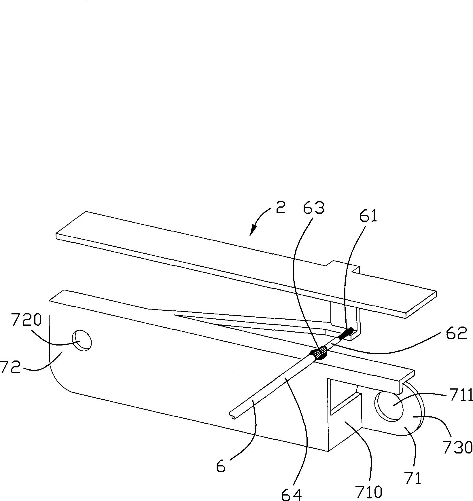
[0017] Such as figure 1 and figure 2 As shown, it is a schematic diagram of different angles of the first preferred embodiment of the present invention. In this embodiment, the multi-frequency antenna 2 of the present invention is formed by bending and cutting a metal sheet, which includes a horizontally arranged plate-shaped radiation part 3, a grounding part 5 spaced apart from the radiation part 3, connecting the radiation part 3 and the grounding part. The connection part 4 and the signal line 6 of the part 5.

[0018] The radiating part 3 is a plate made of conductive material, which is mainly used in wireless local area network (Wireless Local Area Network, WLAN). The radiating part 3 includes a first radiating arm 31 and a second radiating arm 32 extending along the lengthwise direction on the same plane. The first radiation arm 31 works in the frequency band of 4.96GHz-6.00GHz, and the second radiation arm 32 works in the frequency band of 2.2GHz-2.80GHz. The leng...


PUM


Abstract

The invention discloses a multi-frequency antenna (2), comprising a radiation portion (3), a grounding portion (5) provided with the radiation portion at intervals, a connecting portion (4) for connecting the radiation portion and the grounding portion; the radiation portion is a plat, which at least comprises two radiation arms (31, 32) respectively working at two frequency sections or forming a super-side frequency section together; the connecting portion comprises a first connecting arm (41) with one end connected to the radiation portion and a second connecting arm (42) connected to the grounding portion; the first connecting arm and the second connecting arm are mutually connected and formed with a bending position; the first connecting arm and the second connecting arm are formed with a stereo structure which is not in the same plane; the second connecting arm and the grounding portion are in the same plane.

Description

【Technical field】 [0001] The invention relates to an antenna, in particular to a multi-frequency antenna for portable electronic devices such as notebook computers. 【Background technique】 [0002] With the rapid development of communication technology, the miniaturization of communication devices is inevitable. An important factor must be taken into consideration, that is, the design of the antenna must also be miniaturized accordingly. [0003] The planar inverted-F antenna (Planar Inverted-F Antenna PIFA) is a commonly used small antenna suitable for communication terminals such as mobile phones and notebook computers. It adapts to the trend of miniaturization and design simplification of electronic devices, as well as the requirement of antenna miniaturization. One advantage of this type of antenna is that it is easy to implement dual-band, which can effectively reduce the space occupied by the antenna and the manufacturing cost. Another advantage is that the performance...

Claims


Application Information

Patent Timeline
Patent Type & Authority Applications(China)
IPC IPC(8): H01Q1/36H01Q13/08H01Q21/28
Inventor 苏纹枫洪振达戴隆盛柯云龙谷柏冈
Owner FOXCONN (KUNSHAN) COMPUTER CONNECTOR CO LTD
Features
  • R&D
  • Intellectual Property
  • Life Sciences
  • Materials
  • Tech Scout
  • Unparalleled Data Quality
  • Higher Quality Content
  • 60% Fewer Hallucinations
Learn More