Engine with rotary piston

A piston and piston rod technology, applied in the field of reciprocating piston machines, can solve the problems of difficult to filter out impurities, dirty motor parts, difficult time cycle, etc., and achieve the effect of simple maintenance, easy assembly, reduced weight and required space

Inactive Publication Date: 2009-02-18
DEZMOTEC
View PDF0 Cites 6 Cited by
  • Summary
  • Abstract
  • Description
  • Claims
  • Application Information

AI Technical Summary

Problems solved by technology

Reliable operation of conventional engines using biofuels for extended periods of time is very difficult as biofuels always have certain impurities that are difficult to filter out and contaminate or cause motor parts to become dirty

Method used


Image

  • Engine with rotary piston
  • Engine with rotary piston
  • Engine with rotary piston

Examples


Embodiment Construction

[0027] The application of a rotary reciprocating piston machine as a motor or internal combustion engine will now be described. However, as indicated above, the rotary reciprocating piston machine according to the invention can also be operated as a pump or compressor.

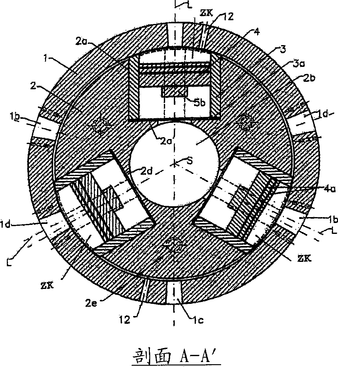
[0028] Furthermore, a rotary reciprocating piston machine will be described below with reference to an embodiment provided with three pistons, but the engine may also be a one or two piston engine, or may be provided with four or more pistons.

[0029] Furthermore, a rotary reciprocating piston machine will be described hereinafter in connection with a star-shaped guide track for two four-stroke work cycles per piston and per rotor revolution. Other guide tracks may also be provided, as described below.

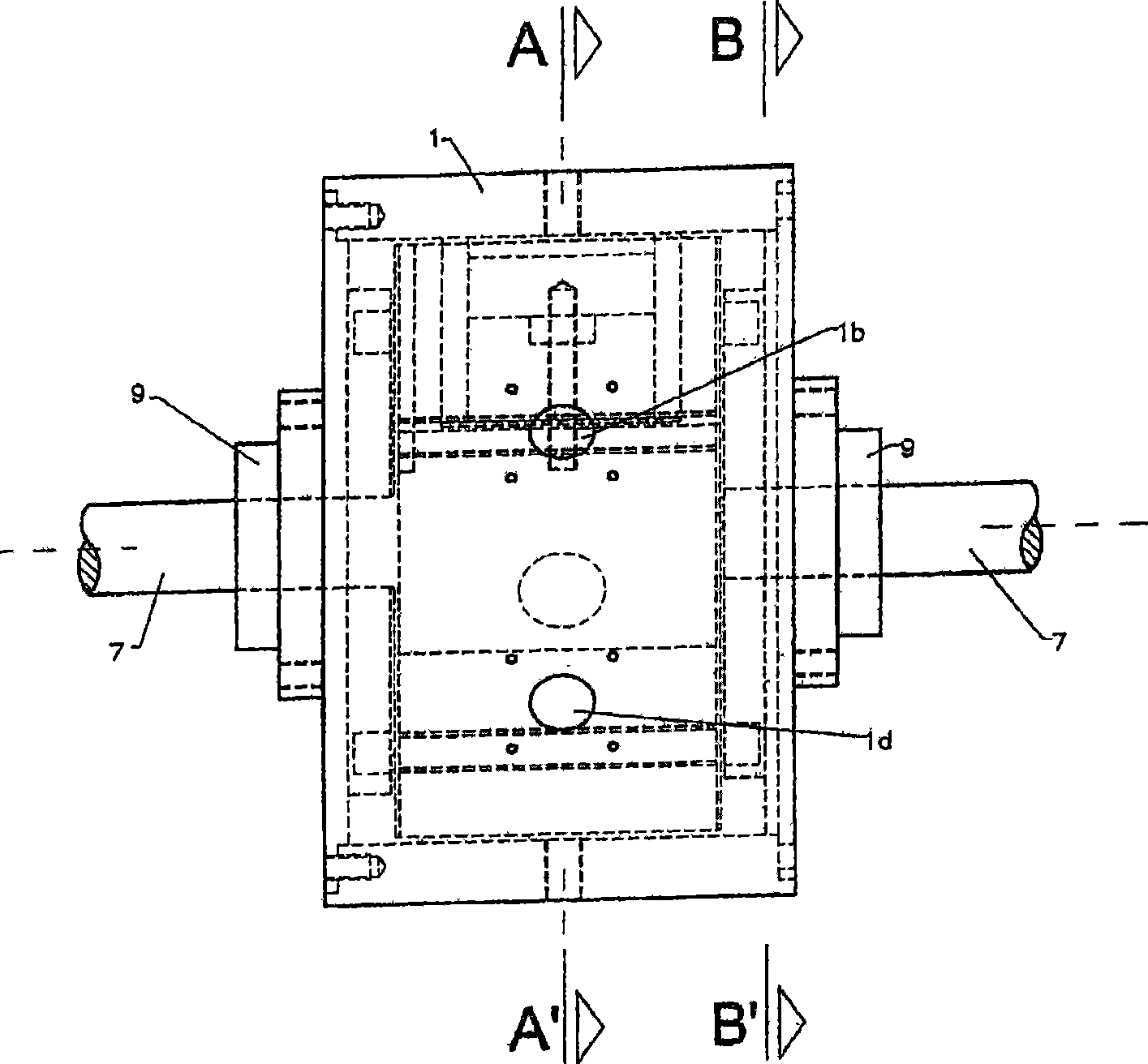
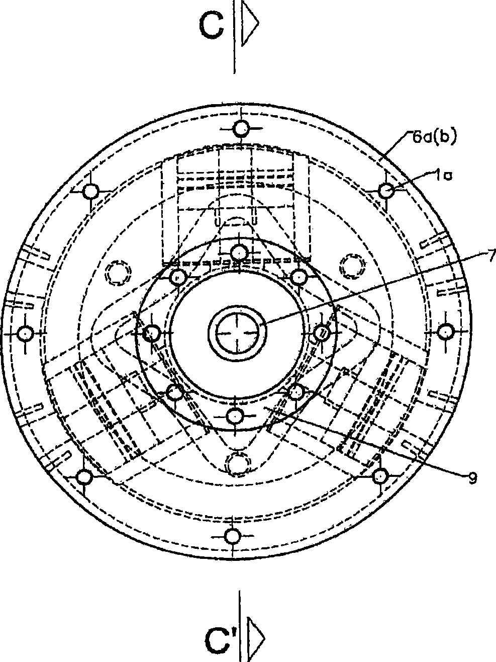
[0030] will now refer to Figures 1 to 8 A rotary reciprocating piston machine is described in more detail. as from Figure 4 As can be seen most clearly in , the rotary reciprocating piston machine has a...


PUM


Abstract

Disclosed is a rotary piston engine comprising a rotor which is rotatably mounted in a housing and in which several pistons can be moved in a radial direction between an outer and an inner dead center. Each piston is provided with a piston rod which sits on a transversal shaft that is fastened to a sliding piece at each end, said sliding piece being movable within radial grooves in the rotor, on both sides of the piston. The external side of the sliding pieces which faces away from the piston is fitted with a pin that is accommodated in a star-shaped continuous guiding groove which is fixed to the housing. The guiding groove extends around an axis of rotation of the rotor and causes the pistons to move in a radial direction between the inner and outer dead centers.

Description

technical field [0001] The present invention relates to a reciprocating piston machine, and more particularly to a rotary reciprocating piston machine, the engine being operable both as a work machine and as an internal combustion engine, in particular a four-stroke internal combustion engine. Background technique [0002] In a conventional reciprocating piston machine, force is usually transmitted by means of an oscillating joint type connecting rod and crankshaft interconnecting the piston. In the cylinder head there are exhaust and intake valves which are driven by one or more camshafts from the crankshaft. Conventional reciprocating piston machines are relatively large in size and assembled from a large number of different engine parts. Reliable operation of conventional engines using biofuels for extended periods of time is very difficult because biofuels always have certain impurities that are difficult to filter out and contaminate or cause motor components to become...

Claims


Application Information

Patent Timeline
Patent Type & Authority Applications(China)
IPC IPC(8): F01B9/06F02B57/08F02B75/22F02B75/32
CPCF01B13/068F01B2009/068F01B2009/066F01B9/06F01B2009/065F02B57/08F01B2009/063
Inventor 汉斯-格尔德·鲁克雷纳·古德拉尔夫·G·利皮恩斯基曼弗雷德·索尼森
Owner DEZMOTEC
Why Eureka
Try Eureka