LED light source structure

A technology of LED light source and LED chip, which is applied in the direction of light source, point light source, light source fixation, etc. It can solve the problems of increasing the cost of LED street lamps, limited irradiation range, and poor brightness uniformity, so as to improve the uniformity of illumination, reduce production costs, The effect of improving the light output rate

Inactive Publication Date: 2009-02-25
ANHUI ZERUN OPTOELECTRONICS
View PDF0 Cites 25 Cited by
  • Summary
  • Abstract
  • Description
  • Claims
  • Application Information

AI Technical Summary

Problems solved by technology

[0003] At present, the main defect of LED as a street light source is that LEDs in street lights need to carry out secondary optical design through external light guide or reflection, so that the illumination range and photometric curve of LED can meet the needs of long rectangular road lighting, which not only increases Reduce the cost of LED street lamps, and lead to secondary light loss of LEDs at the same time
In actual use, because the light emitted by the LED light source has a directional characteristic, it is a light source with a certain directional projection, so limited by the directional light output of the LED, the combined street lamp body’s irradiation range is still limited, and the central area of ​​the lamp pole of the street lamp The illumination brightness is high, while the edge area away from the center is darker, and the brightness uniformity in its effective illumination range is poor

Method used


Image

  • LED light source structure
  • LED light source structure
  • LED light source structure

Examples


Embodiment Construction

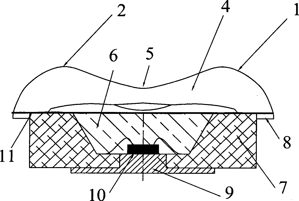
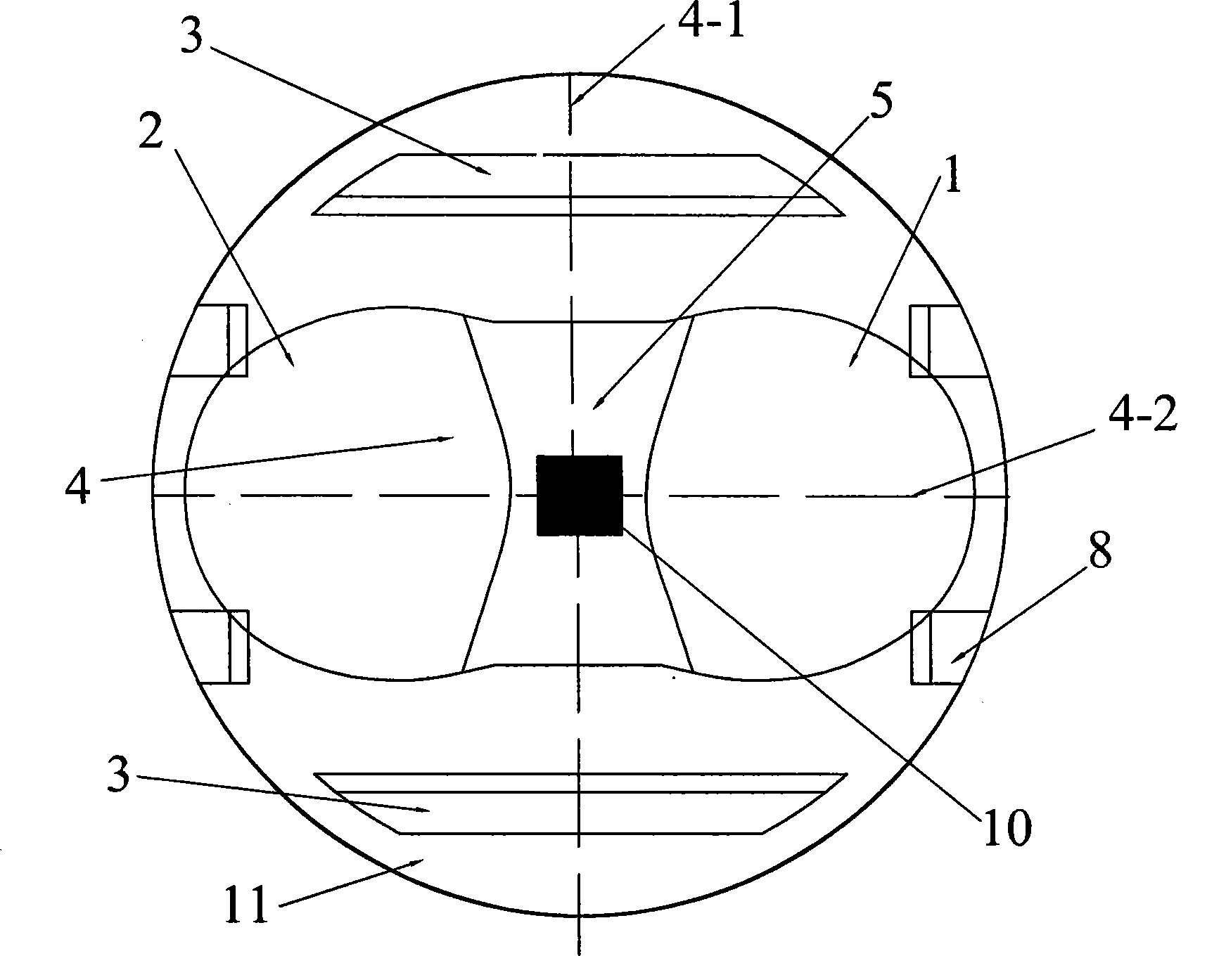
[0017] Such as figure 1 , 2 As shown, the lens 4 made of silicone resin material is installed on the smooth upper plane 11 of the heat-conducting bracket 7, the bracket 7 is injection molded by high-temperature nylon material, the bottom of the lens 4 is flat with the upper plane 11 of the bracket 7, and the lens 4 passes through 4 A boss 8 is closely bonded to the support 7. The LED chip 10 is packaged in the cavity formed by the bracket 7 and the lens 4 . A reflection cup 6 is fixed in the cavity of the bracket 7, and the reflection cup 6 is filled with a mixture of silica gel and fluorescent powder with a refractive index of 1.53, and the mixture is cured and formed in advance. The LED chip 10 is located at the center of the bottom of the reflective cup 6 and is fixed on the heat conduction seat 9 at the bottom of the support 7 .

[0018] The upper surface of the lens 4 is two connected semi-ellipsoids or hemispherical structures, the semi-ellipsoid or hemispherical stru...


PUM


Abstract

The invention discloses an LED light source structure, which comprises a bracket, a lens arranged on the upper plane of the bracket and an LED chip encapsulated in a cavity formed by the bracket and the lens. The upper surface of the lens is two connecting semi-ellipsoidal surfaces or semi-spherical surfaces; the two connecting semi-ellipsoidal surfaces or semi-spherical surfaces are symmetrically distributed along the central axis of the LED chip and the meeting surface of the two connecting semi-ellipsoidal surfaces or semi-spherical surfaces is a long and narrow surface; two reflex arc-shaped lug bosses are symmetrically arranged on the two sides of the short axis extension line located on the semi-ellipsoidal surfaces or the semi-spherical surfaces and fixedly arranged on the upper plane of the bracket. The invention ensures that the light extraction shape of the light emitted by the side surface of the LED chip can be changed through the refraction and reflection of the lens, and the light can gather and be distributed according to a rectangular irradiation surface, thereby reducing the secondary refraction and reflection of the beams, improving light outgoing rate and illumination uniformity, and realizing an irradiation road surface without light spots, dark areas and blinding glares.

Description

technical field [0001] The invention relates to an LED light source structure for an LED street lamp. Background technique [0002] As a semiconductor light-emitting material, LED (light-emitting diode) has the characteristics of energy saving, environmental protection, good color rendering, and stable light emission. Compared with other light-emitting materials, it will gradually replace traditional lamps with its advantages of green, high efficiency, reliability, and durability. . LED street lamps are combined with multiple high-power LED light sources and distributed in the form of a plane dot matrix. Secondary optical light distribution is performed through external lenses or reflective cups to control the distribution range of light, and the emitted light becomes a long strip of light. Spread along the direction of the road to meet the needs of road lighting. [0003] At present, the main defect of LED as a street light source is that LEDs in street lights need to car...

Claims


Application Information

Patent Timeline
Patent Type & Authority Applications(China)
IPC IPC(8): F21V5/04F21V17/10F21V7/04F21W131/103F21Y101/02F21Y115/10
CPCF21V5/04H01L33/58F21Y2101/02F21W2131/103F21Y2115/10
Inventor 周广跃
Owner ANHUI ZERUN OPTOELECTRONICS
Why Eureka
Try Eureka