

Solar cell module and method for manufacturing the same
A technology of solar cells and manufacturing methods, applied in the direction of final product manufacturing, sustainable manufacturing/processing, circuits, etc., can solve the problem of smaller bonding area between wiring materials and solar cells, lower solar cell collection efficiency, and wiring material Problems such as decreased adhesion
- Summary
- Abstract
- Description
- Claims
- Application Information
AI Technical Summary
Problems solved by technology
Method used
Image

Examples
no. 1 approach
[0032] (Schematic structure of a solar cell module)
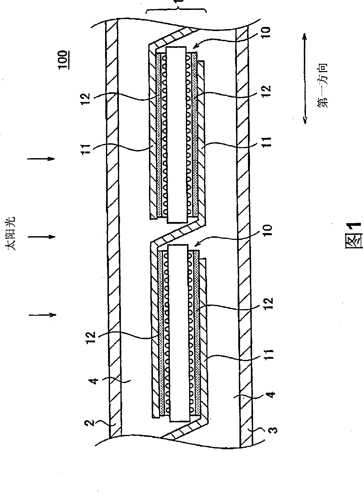
[0033] Referring to FIG. 1 , a schematic configuration of a solar cell module 100 according to a first embodiment of the present invention will be described. FIG. 1 is an enlarged side view of a solar cell module 100 according to this embodiment.
[0034] The solar cell module 100 includes a solar cell string 1 , a light-receiving surface side protector 2 , a rear side protector 3 , and a sealing member 4 . The solar cell module 100 is constituted by sealing the solar cell string 1 between the light-receiving surface side protector 2 and the back side protector 3 .
[0035] Solar cell string 1 includes a plurality of solar cells 10 , wiring material 11 and resin adhesive 12 . A solar cell string 1 is formed by interconnecting a plurality of solar cells 10 arranged in the first direction through a wiring material 11 .
[0036] The solar cell 10 has a light-receiving surface on which sunlight is incident, and a back surfac...
no. 2 approach
[0097] Next, a second embodiment of the present invention will be described with reference to the drawings. This embodiment differs from the first embodiment described above in that the bus bar electrode has a protrusion protruding toward the wiring material. Therefore, the description of the same or similar parts as those of the above-mentioned first embodiment will be omitted below.
[0098] (Structure of Solar Cell String)
[0099] refer to Figure 7 , the structure of the solar cell string 1 of the present embodiment will be described. Figure 7 for Figure 4 An enlarged cross-sectional view of the B-B line.
[0100] Such as Figure 7 As shown, the bus bar electrode 40 of this embodiment has the protrusion part 40a formed in convex shape toward the wiring material 11. As shown in FIG. The protruding portion 40 a is formed at an end portion in the second direction in the bus bar electrode 40 . The protruding portion 40 a is embedded in the soft conductor 11 b include...
no. 3 approach
[0114] Next, a third embodiment of the present invention will be described using the drawings. This embodiment differs from the first embodiment described above in that the solar cell of this embodiment does not have a bus bar electrode as a collector electrode. Therefore, in the following description, the description of the parts that are the same as or similar to those of the above-mentioned first embodiment will be omitted.
[0115] (Schematic structure of a solar cell module)
[0116] A schematic configuration of a solar cell module 200 according to the present embodiment will be described with reference to FIG. 8 . FIG. 8 is an enlarged side view of the solar cell module 200 of this embodiment.
[0117] The solar cell string 60 is sealed between the light-receiving surface side protector 2 and the back side protector 3 with the sealant 4 , thereby constituting the solar cell module 200 .
[0118] Solar cell string 60 has a plurality of solar cells 70 , wiring material ...
PUM
 Abstract
Description
Claims
Application Information