
Belt with projection

A conveyor belt and support technology, applied in the field of conveying conveyor belts

Active Publication Date: 2011-06-08
BANDO CHEM IND LTD
View PDF8 Cites 0 Cited by
  • Summary
  • Abstract
  • Description
  • Claims
  • Application Information

AI Technical Summary

Problems solved by technology

In terms of directionality, if the linear perforation is not performed parallel to the longitudinal direction of the conveyor belt, there will be wrinkles on the formed protruding members, and there is a danger that the correct conveying direction will not be obtained.

Method used


Image

  • Belt with projection
  • Belt with projection
  • Belt with projection

Examples


Embodiment 1、2

[0179]

[0180] Figure 7 Among (a) to (d), examples of Example 1 are shown.

[0181] This embodiment is an example of piercing and inserting the U-shaped needle-shaped body relative to the convex support portion along the length direction of the conveyor belt. The pricking operation uses a pliers-shaped clamp to hold the U-shaped curved part to keep the state stable and complete the pricking operation reliably at the specified position.

[0182] In this example, a wire 11 (figure (a)) with a width of 0.5 mm and a thickness of 0.3 mm was bent to a metal U-shaped needle 12 (figure (b)) with an inner width of 2 mm and a leg length of 5 mm. As the wire, for example, a staple (JIS G6035) wire of a stapler can be used. When the front end is made into an acute angle, the piercing property can be improved.

[0183] This U-shaped needle-shaped body 12 is pierced and inserted into the convex support member 4 (figure (c)). The insertion position is centered on the central part of ...

Embodiment 2

[0186] Figure 7 (e) shows an example of Embodiment 2.

[0187] This embodiment is an example in which the front end side of the U-shaped needle-like body protruding through the piercing is bent to intersect the two ends in the first embodiment to provide an intersecting portion 13 . Bending can also bend both sides, or bend one side, or twist. In this example, the bent portion, that is, the leg length may also be lengthened.

Embodiment 3

[0202] It is opened in the central part of the convex support part 4 along the length direction of the conveyor belt The through-hole 15 of 2mm is an example in which one needle-shaped body 14 is stabbed and inserted in another part at the same time.

[0203] In this example, as a result of the fall recovery test, similar to the examples 1 and 2, the recovery property was confirmed.


PUM


Abstract

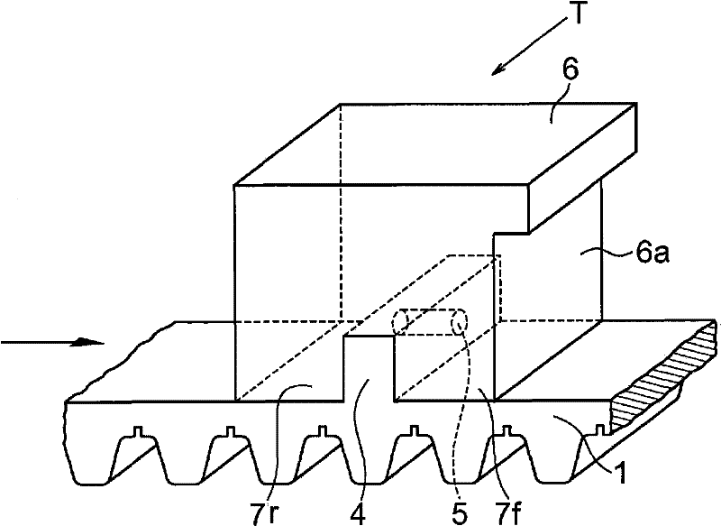
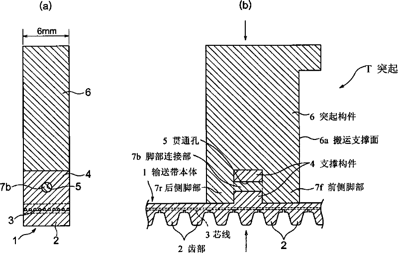
A belt with projections produced by providing a thermosetting resin belt provided on its backside with protrudent support portions and unifying resin projections with the protrudent support portions through injection molding, wherein for enhancing of the bonding strength of the resin projections, U-shaped needlelike matter having been stab inserted in each of the protrudent support portions of the belt is used as means for bonding of the resin projections with the protrudent support portions.

Description

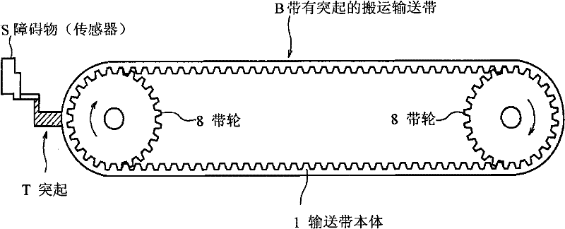
technical field [0001] The present invention relates to a conveying conveyor belt with protrusions provided with protrusions on the back of the conveyor belt. The protrusions serve as gaps between articles when the articles are conveyed by the back of the conveyor belt, or to activate a sensor that detects the travel position of the conveyor belt to push the articles to move. Background technique [0002] When forming protrusions on the back of the conveyor belt, the present applicant previously proposed the following technical proposal: a through hole is provided on the support part integrally uprightly arranged on the back of the conveyor belt, and the support part with the external fitting or clamping A pair of legs are fixed to the protruding member of the support part, and a leg connection part is integrally provided to fill the through hole communicating with the support part and connect the two legs (Patent Document 1: Japanese Patent No. 3449415). refer to image 3 ...

Claims


Application Information

Patent Timeline
Patent Type & Authority Patents(China)
IPC IPC(8): B65G15/42B65G15/30B65G15/44
CPCB65G15/42
Inventor 大田隆史生熊健二
Owner BANDO CHEM IND LTD
Learn More