In solder covered copper foil ribbon conductor wire and its connection method

A strip wire, tinned copper foil technology, applied in welding media, welding equipment, welding/cutting media/materials, etc., to achieve the effect of reducing usage and alleviating deformation

Inactive Publication Date: 2010-12-08
太阳能先锋株式会社
View PDF9 Cites 1 Cited by
  • Summary
  • Abstract
  • Description
  • Claims
  • Application Information

AI Technical Summary

Problems solved by technology

[0010] In addition, the electronic devices such as semiconductors described in the above patent documents 1 to 4 are mounted on substrates other than glass substrates such as printed circuit boards or plastic resin substrates. However, there are great differences in the material of the electrode film (or layer) or the conductive film (or layer), the thickness of the film (or layer), and the mechanical strength, and it is difficult to mount the semiconductor on the above-mentioned substrate other than the glass substrate. The conductor connection method of the electronic device such as is directly transferred to the conductor connection method of the electronic device installed on the glass substrate of the present invention

Method used


Image

  • In solder covered copper foil ribbon conductor wire and its connection method
  • In solder covered copper foil ribbon conductor wire and its connection method
  • In solder covered copper foil ribbon conductor wire and its connection method

Examples


Embodiment Construction

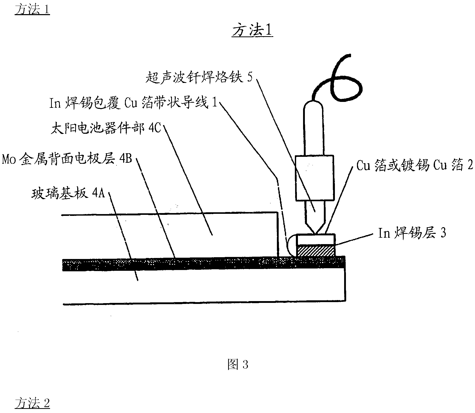
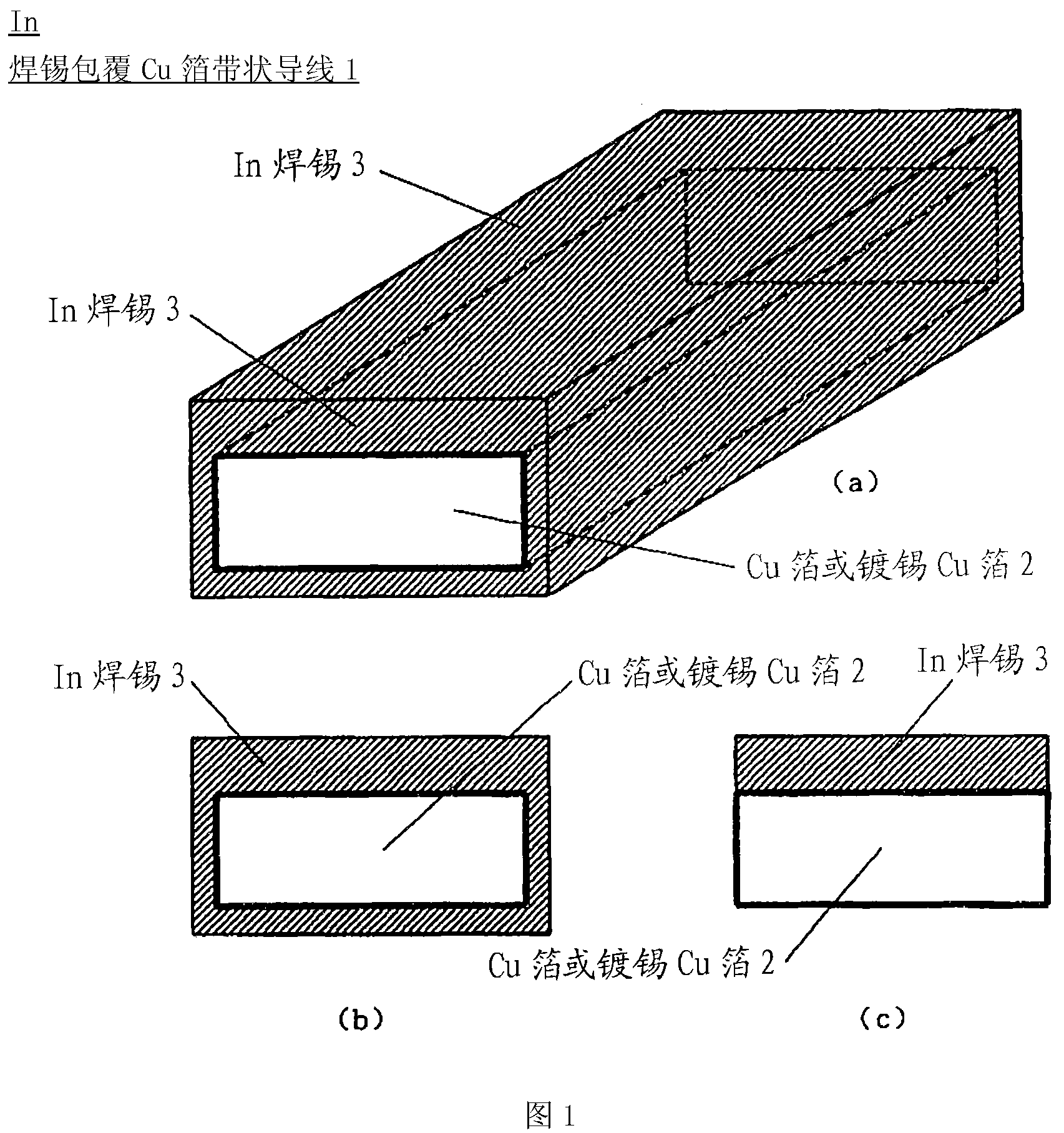
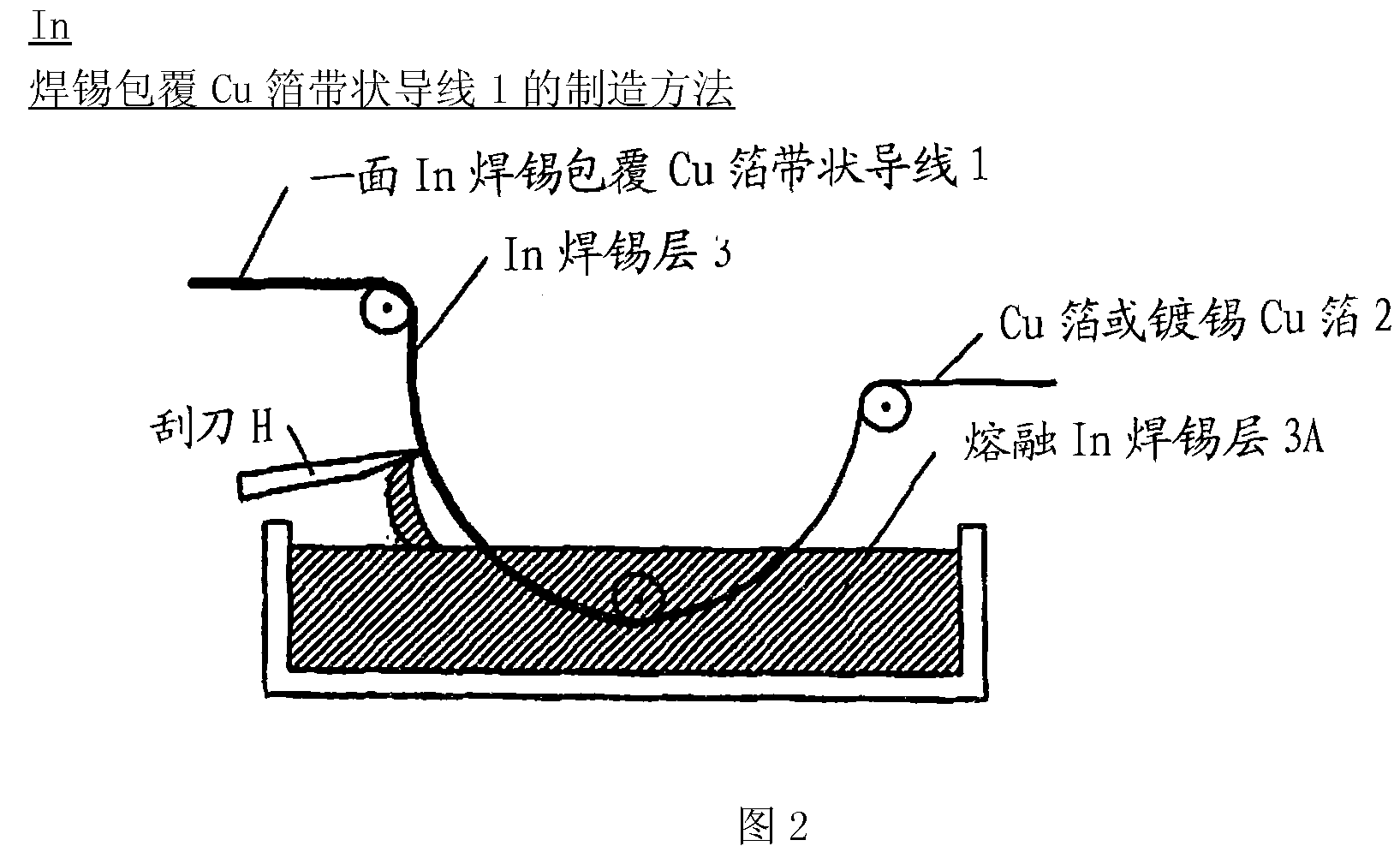
[0036] The present invention relates to an electrode film (or layer) or conductive film ( or layer) In solder-clad copper foil ribbon wires that are conductor-connected to ribbon wires (copper foil or tinned copper foil ribbon wires) and In solder or In solder-clad tinned copper foil ribbon wires conductor connection method.

[0037] Since the electrode film (or layer) or conductive film (or layer) of the above-mentioned electronic device is formed on the glass substrate, therefore, its material uses metals such as Mo or ITO (transparent conductive film) other than Cu, and the film (or layer) The thickness is extremely thin, the mechanical strength is low, and it is easy to break.

[0038] Therefore, the solder used for conductor connection of an electronic device mounted on a substrate other than a glass substrate, or a conductor connection method using the solder cannot be directly used.

[0039] Therefore, first of all, electrode films or conductive films and strip wires ...


PUM

PropertyMeasurementUnit
thicknessaaaaaaaaaa
thicknessaaaaaaaaaa
thicknessaaaaaaaaaa

Abstract

The invention provides an In tin-coated copper foil stripe lead and connecting method thereof. The method tenaciously connects a conductor electrode on a glass substrate to a ribbon conductor with certainty at low cost without causing damage. An indium-solder-coated copper foil ribbon conductor (1) obtained by depositing an indium solder (3) (100-90% indium and 10-0% silver) in a thickness of 100um or smaller on one side of a copper foil or tin-coated copper foil (2) having a thickness of 300 um or smaller and optionally further depositing the solder thinly on the other surfaces of the foil is placed on an exposed part of a molybdenum-based metallic back electrode layer (4B) on a glass substrate (4A). An ultrasonic soldering iron (5) is then placed against the upper side of the copper foil ribbon conductor (1) to melt the indium solder (3) and connect the copper foil ribbon conductor 1 to the electrode layer (4B). Another method includes soldering an indium solder (3) (having the same composition as shown above) to the electrode layer (4B) beforehand, subsequently placing a ribbon-form copper foil or tin-plated copper foil (2) thereon, and connecting the copper foil (2) to the electrode layer 4B with an ultrasonic soldering iron (5).

Description

technical field [0001] The present invention relates to an In (indium) solder coated copper foil ribbon wire for connecting conductors of an electronic device mounted on a glass substrate and a connection method thereof. Background technique [0002] When an electronic device such as a semiconductor component is mounted on a substrate other than a glass substrate such as a printed circuit board or a plastic resin substrate, when connecting the electrodes of the electronic device to the circuit wiring on the substrate, when connecting the above-mentioned circuit wiring and external electrodes At that time, in consideration of environmental issues, properties of substrate materials, electrodes, circuit wiring and other materials, and productivity, we developed special solder materials and soldering methods that avoid the use of lead-containing solder. [0003] For the connection of the electrodes of the semiconductor device on the electronic device such as the above-mentioned...

Claims


Application Information

Patent Timeline
Patent Type & Authority Patents(China)
IPC IPC(8): H01L31/042H01L31/04C23C2/14C22C28/00B23K35/26G02F1/1345
CPCH01L2924/01014H01L31/05H01L24/43H01L2924/01047H01L2224/45032H01L2924/014C23C26/02H01L2224/45014H01L2924/0105H01L2924/01029H01L2224/45639C23C28/023H01L24/745H01L2224/45147H01L2224/43H01L2224/45565H01L2924/01005H01L2924/01082H01L2924/01075H01L2924/01033H01L2924/01049C23C28/00H01L2924/01004H01L2924/10253C22C28/00H01L24/45Y02E10/50H01L2924/01006H01L2224/745H01L2924/01078H01L2924/01042H01L2224/45609B23K35/26H01L31/0508H01L31/0512H01L2924/00011H01L2924/00014H01L2924/01015H01L2924/15788Y02E10/541Y10T29/49117Y10T29/532Y02P70/50H01L2924/00H01L2224/48H01L2924/206G02F1/1345
Inventor 田泽健一
Owner 太阳能先锋株式会社
Why Eureka
Try Eureka