Fluorescence endoscopic imaging method and device

An imaging device and fluorescence image technology, applied in the field of medical diagnosis, can solve problems such as long image acquisition time, complex system structure, and limited application range, and achieve the effects of easy operation and promotion, simple device structure, and convenient data processing

Inactive Publication Date: 2010-12-15
JIANGSU TIANNING PHOTON TECH
View PDF3 Cites 0 Cited by
  • Summary
  • Abstract
  • Description
  • Claims
  • Application Information

AI Technical Summary

Problems solved by technology

However, the smallest tumors found by conventional endoscopic examinations are generally around 10 mm. How can we find smaller tumors simply and clearly in endoscopic examinations, and even realize non-destructive, real-time, biopsy, cell Horizontal imaging is the biggest problem in the development of endoscopic diagnosis
However, traditional laser scanning confocal endoscopes generally use complex three-dimensional scanning imaging methods to obtain three-dimensional images of samples, and the image acquisition time is long; the system structure is complex; and the price is expensive, which limits the application of this technology
However, traditional two-photon excitation fluorescence endoscopes mostly use scanning galvanometers to control the scanning of a single beam on the sample, and the recording time is on the order of seconds, which leads to the fact that this technology can only be used to observe biological process, which largely limits its scope of application
In addition, the second harmonic endoscopy technology faces multiple challenges such as single-point scanning of two-photon fluorescence endoscopy, long imaging time, and complex systems.
These technologies usually use single-point scanning of illuminating lasers, rather than efficient multi-point array scanning, so there are still major drawbacks

Method used


Image

  • Fluorescence endoscopic imaging method and device
  • Fluorescence endoscopic imaging method and device
  • Fluorescence endoscopic imaging method and device

Examples


Embodiment Construction

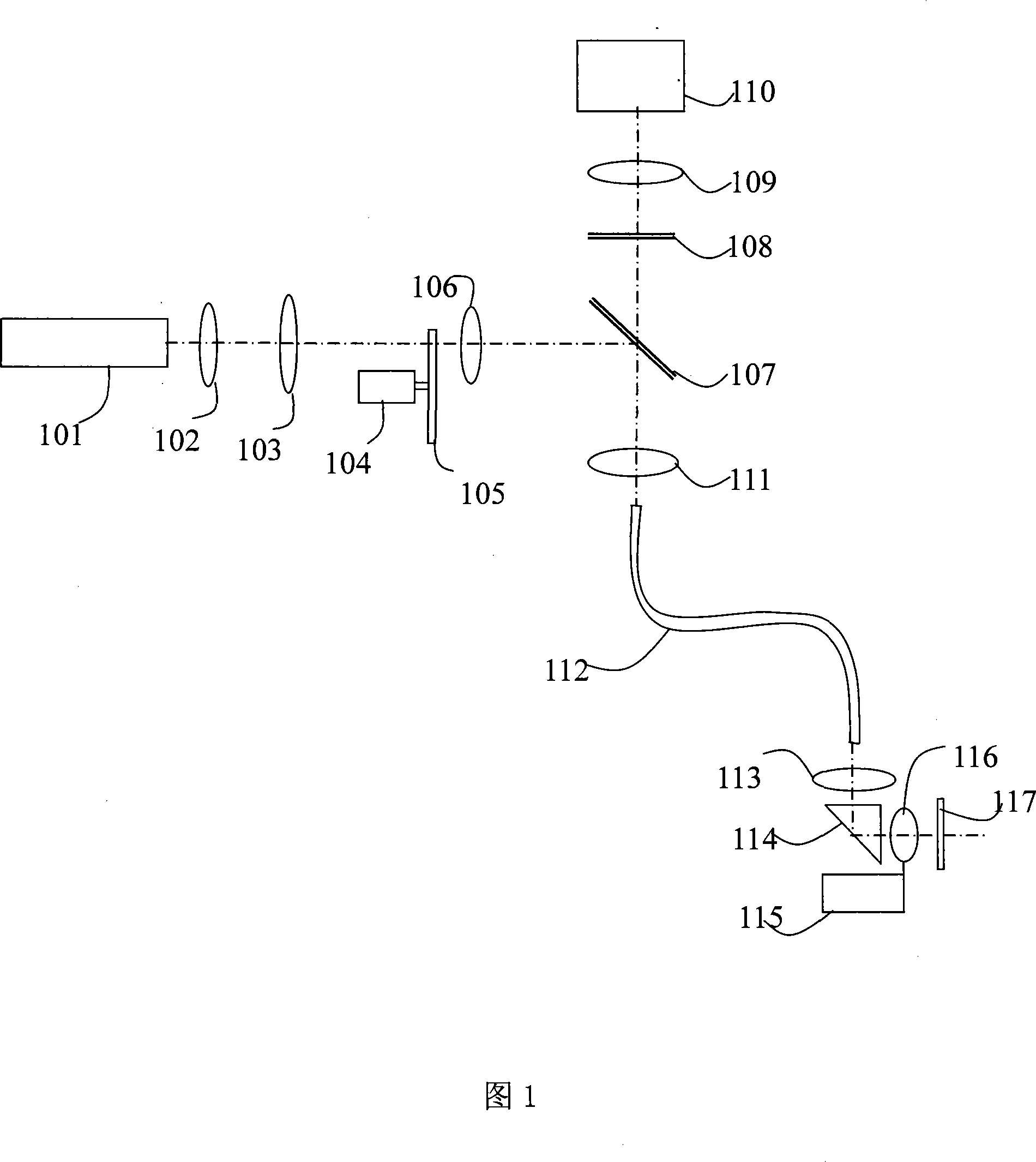
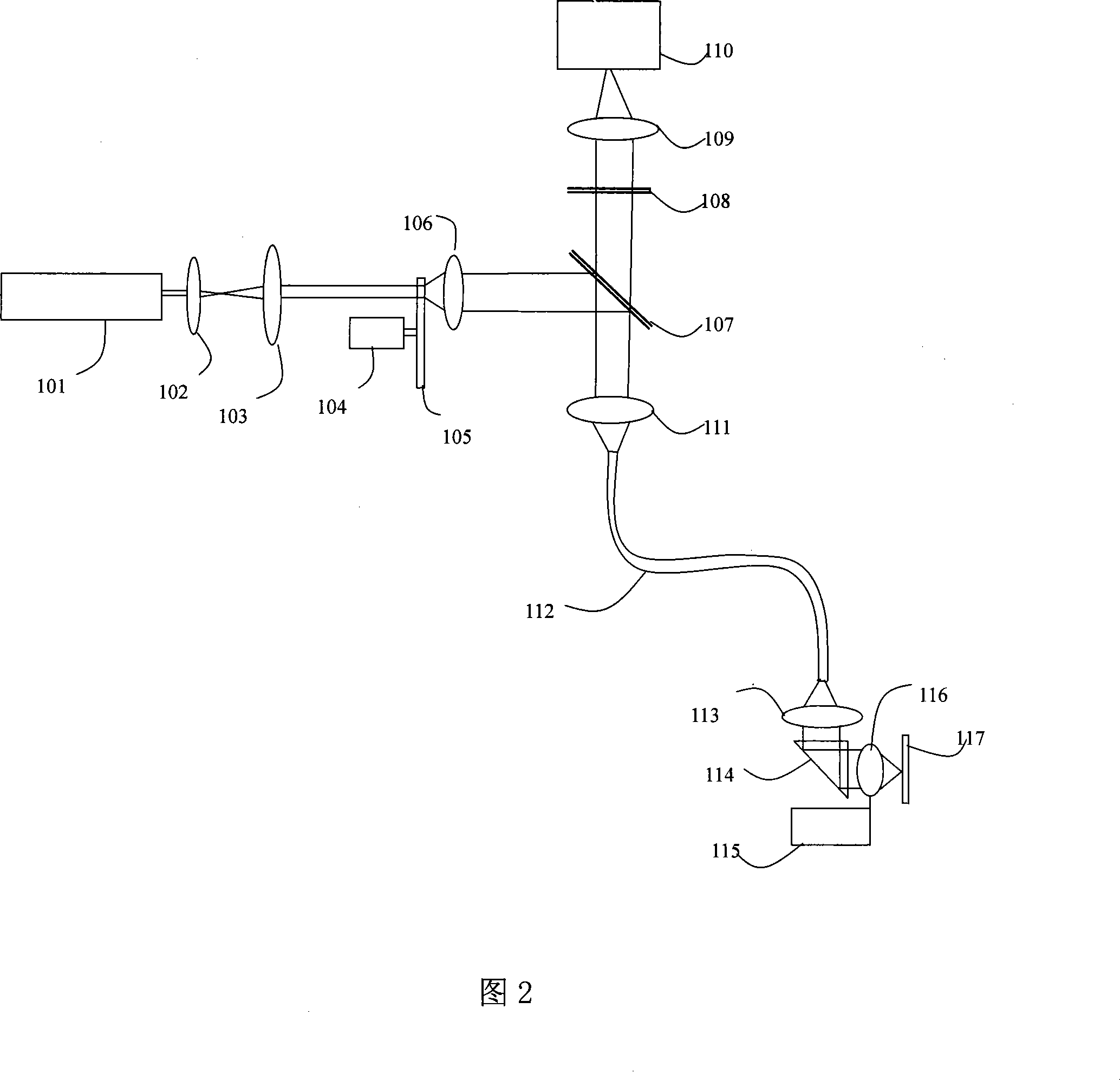
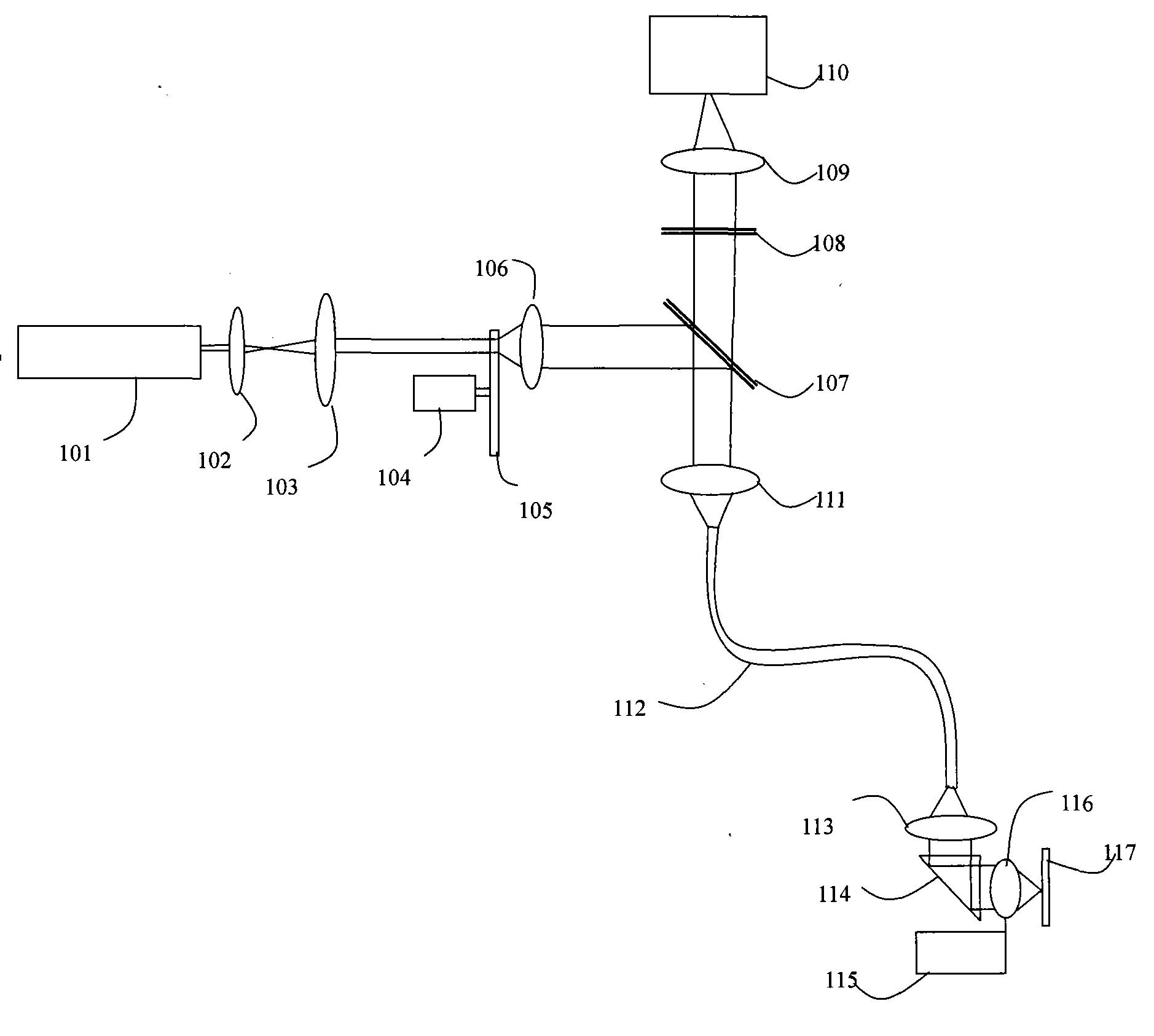
[0043]A fluorescent endoscopic imaging method for imaging a tissue to be measured in a human body, comprising the following steps: first, a speckle image is generated by a speckle image generating unit, and the speckle image is used to excite a fluorescent image on the tissue to be measured; Then the speckle image is transmitted from outside the body to the body through the light transmission unit; then the speckle image transmitted into the body is focused on the tissue to be measured through the objective lens at the end of the light transmission unit to excite a fluorescent image; the generated The fluorescence image then enters the light conduction unit in the reverse direction and is transmitted to the outside of the body, and is finally separated by the spectroscopic unit and recorded by the image acquisition unit to generate a fluorescence image for analysis and processing by the image analysis and processing unit. The image acquisition unit is a digital camera or a digi...


PUM


Abstract

The invention discloses a method and a device for fluorescence endoscopic imaging. The technical scheme is as follows: a speckle image producing unit produces a speckle image; a light transmission unit is coupled with the speckle image producing unit, and one end of the light transmission unit can be inserted at an tissue to be tested inside a body; the light transmission unit focuses the speckleimage on the tissue to be tested through an object lens positioned at the end of the light transmission image to activate a fluorescence image, and reversely sends the fluorescence image out of the body; a light distribution unit separates the fluorescence image at the outer end of the light transmission unit from a light path; an image acquisition unit coupled with the light distribution unit records the fluorescence image; and an image analyzing and processing unit processes and analyzes the recorded fluorescence image. The method for fluorescence endoscopic imaging can conduct scatheless and high spatial resolution imaging on the tissue to be tested at a cell level in a wide-field way, the post-processing of data is easy, and the speed of imaging is high. The device for fluorescence endoscopic imaging is simple-structured and cost-effective.

Description

technical field [0001] The invention relates to the field of medical diagnosis, in particular to a fluorescent endoscopic imaging method and device. Background technique [0002] Early detection is key to improving cancer survival rates. However, the smallest tumors found by conventional endoscopic examinations are generally around 10 mm. How can we find smaller tumors simply and clearly in endoscopic examinations, and even realize non-destructive, real-time, live tomography, cell Horizontal imaging is the biggest problem in the development of endoscopic diagnosis. However, traditional laser scanning confocal endoscopes generally use complex 3D scanning imaging methods to obtain 3D images of samples. The image acquisition time is long; the system structure is complex; and the price is expensive, which limits the application of this technology. However, traditional two-photon excitation fluorescence endoscopes mostly use scanning galvanometers to control the scanning of a s...

Claims


Application Information

Patent Timeline
Patent Type & Authority Patents(China)
IPC IPC(8): A61B1/05
Inventor 邵永红屈军乐赵羚伶牛憨笨
Owner JIANGSU TIANNING PHOTON TECH
Why Eureka
Try Eureka