Electric screw press

An electric screw and press technology, applied in forging presses, forging presses, forging/pressing/hammer devices, etc., to achieve the effect of reducing power

Inactive Publication Date: 2010-12-08
SHANGHAI YUNLIANG FORGING PRESS
View PDF2 Cites 3 Cited by
  • Summary
  • Abstract
  • Description
  • Claims
  • Application Information

AI Technical Summary

Problems solved by technology

However, because the flywheel of this machine is always accelerated from zero every time it strikes, the acceleration of the slider is limited, and it is difficult to obtain a high striking speed, so the energy consumption is relatively large

Method used


Image

  • Electric screw press
  • Electric screw press
  • Electric screw press

Examples


Embodiment Construction

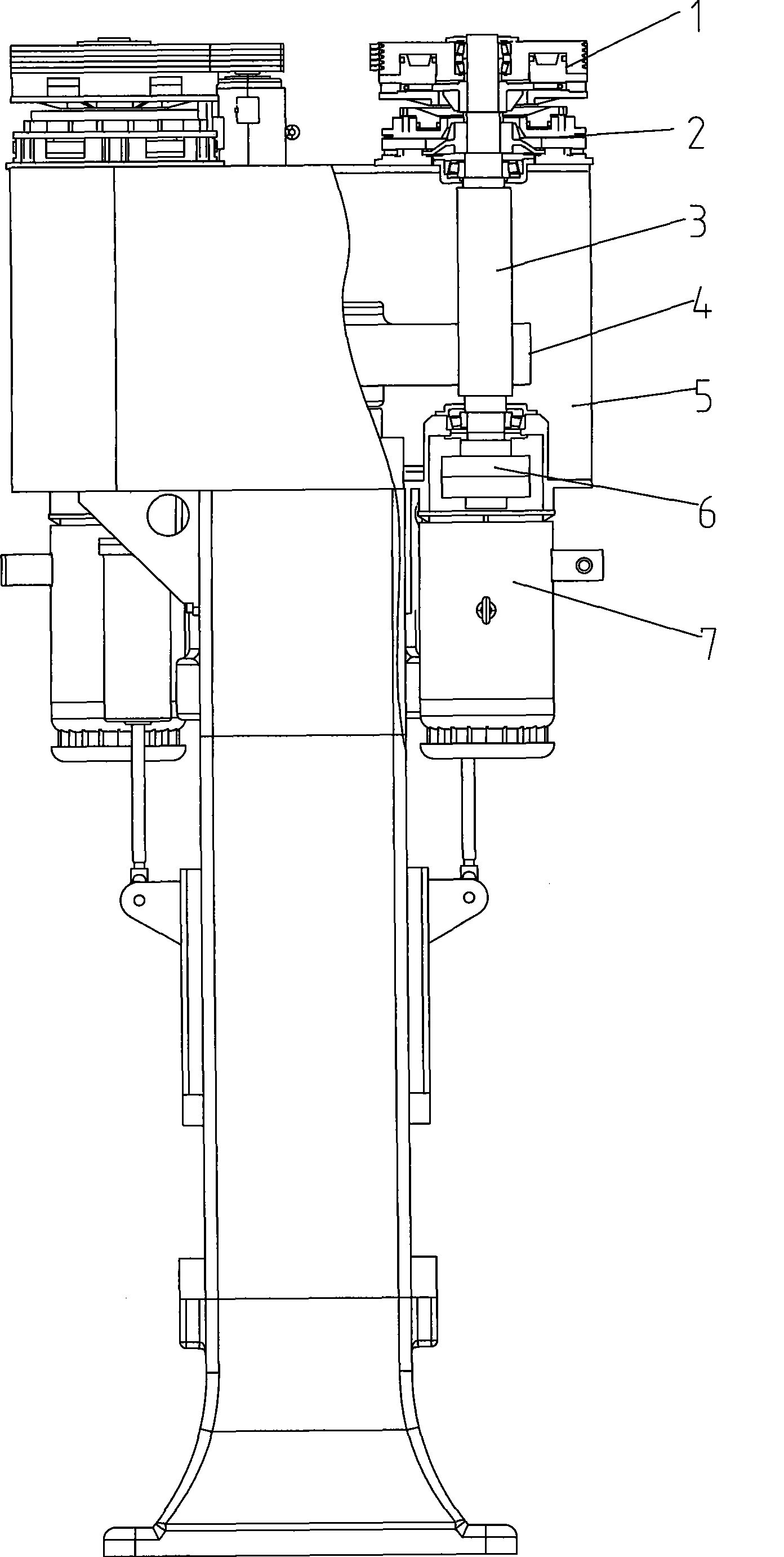
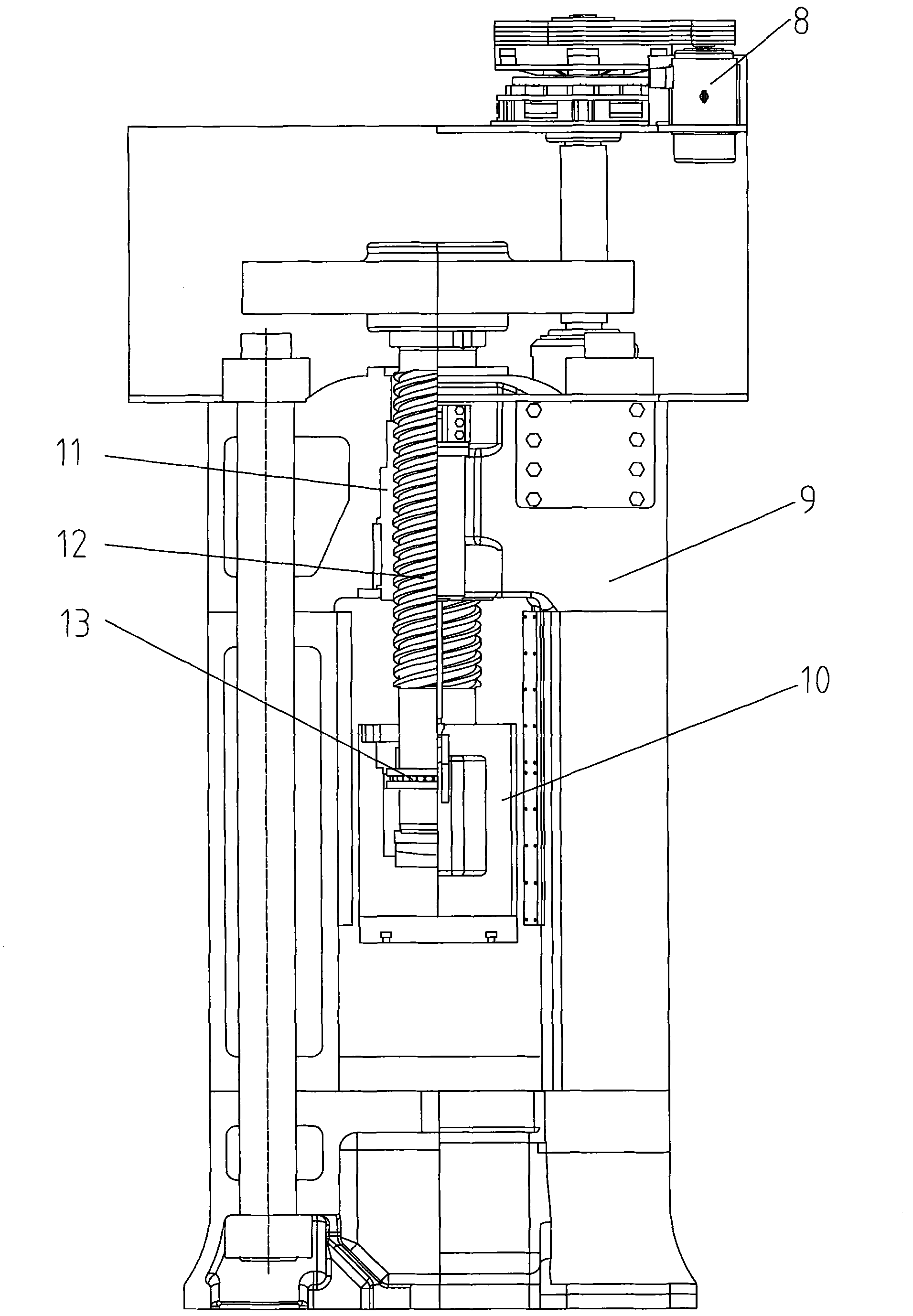
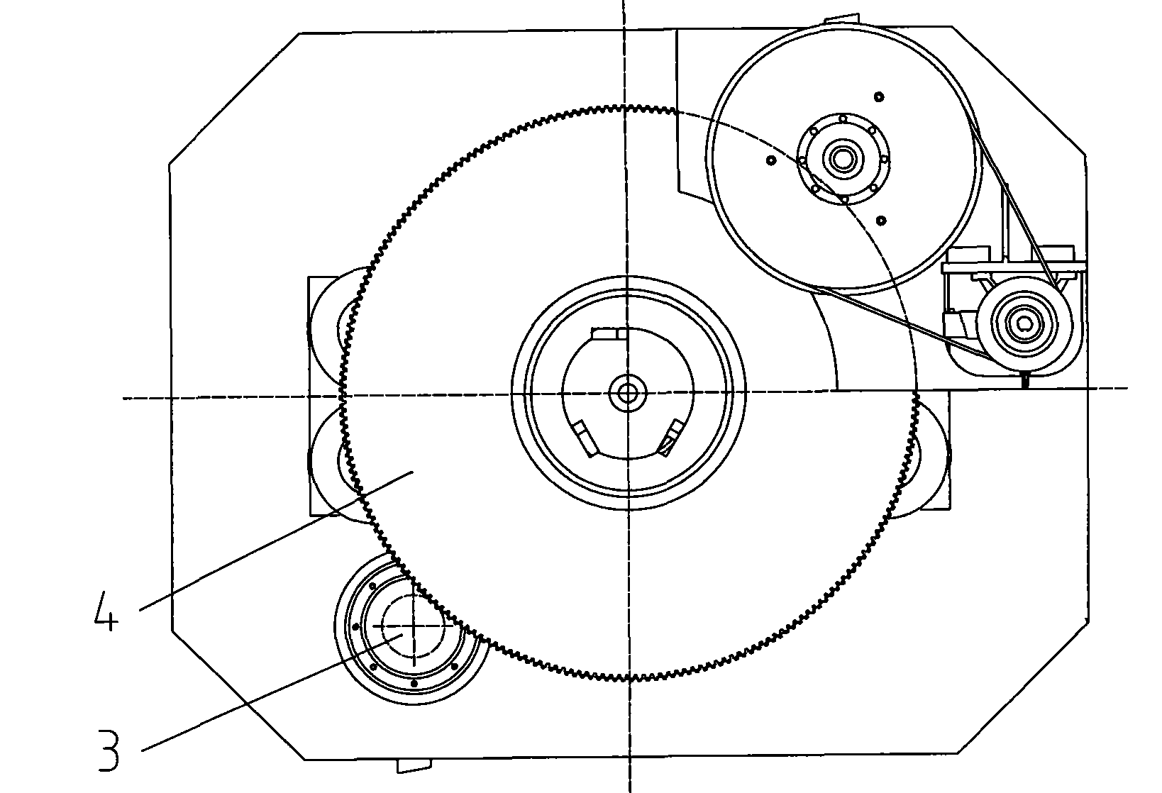
[0019] Such as Figure 1-3 As shown, a gear box 5 is installed above the support 9, and the pinion 3 is rotatably located in the gear box 5. The outer rim of the press flywheel 4 is processed into a large gear, which meshes with the pinion 3. There can be even numbers of pinions 3, which are arranged symmetrically around the flywheel 4 along the circumferential direction, see image 3 , pinion 3 has two. The lower end of the pinion 3 is connected with the first motor 7 through a safety clutch 6 . The upper end of the pinion 3 is equipped with a brake 2 and a clutch 1 . The brake 2 is fixed on the gear box 5, the clutch 1 is fixed on the pinion shaft, and is driven to rotate by the second motor 8 installed on the gear box 5. Preferably, the second motor 8 is an ordinary motor, and the clutch 1 can be connected with the small gear. Gear 3 is connected or disengaged. The flywheel 4 is connected with the screw rod 12, and the screw rod 12 is installed in the beam and forms a ...


PUM


Abstract

The invention relates to an electric screw press machine which comprises a motor base, a first motor, a fry wheel which horizontally rotates a small gear, a second motor and a clutch. The outer edge of the fry wheel is gear-shaped; the small gear is meshed with the fry wheel; the first motor is connected with the small gear; and the second motor is arranged on the motor base and connected with the small gear by the clutch. By controlling the closing and the separation of the clutch and the small gear, the screw press machine can not only reasonably distribute energy, but also accelerate the rotating fry wheel in a short time, thereby causing that a sliding block has a higher hitting speed, the power of a motor is reduced, and the energy-saving effect is achieved.

Description

technical field [0001] The invention relates to a screw press, in particular to an electric screw press. Background technique [0002] In the traditional electric screw press, the small gear mounted on the servo motor is meshed with the flywheel processed into a large gear, the flywheel is connected with the screw, and the screw and the nut installed in the slider form a thread pair. The servo motor installed on the machine body directly drives the flywheel to rotate, and then drives the slider to move up and down. The presetting of strike energy is achieved by controlling the rotation speed of the servo motor, and the strike and recovery of the machine tool slider are realized by controlling the steering of the servo motor. Since the kinetic energy is provided by the servo motor, the preset strike energy can be obtained through microcomputer control. But this machine always accelerates from zero because every time it strikes the flywheel, so the acceleration of the slider...

Claims


Application Information

Patent Timeline
Patent Type & Authority Patents(China)
IPC IPC(8): B21J9/00B21J9/18
Inventor 陆友荣龚伟兴
Owner SHANGHAI YUNLIANG FORGING PRESS
Why Eureka
Try Eureka