Medical cutting tool manufacturing apparatus and method

A technology for manufacturing devices and manufacturing methods, applied in the field of manufacturing devices for medical cutting tools, capable of solving problems such as shaking, increasing the clearance of sliding parts, and spherical deformation, and achieving the effects of cost reduction, shape change prevention, and structural simplification

Inactive Publication Date: 2009-03-04
MATSUTANI SEISAKUSHO CO LTD
View PDF0 Cites 5 Cited by
  • Summary
  • Abstract
  • Description
  • Claims
  • Application Information

AI Technical Summary

Problems solved by technology

[0007] However, in order to move the rotating grindstone 16, a gap is required in the sliding part of the grindstone 16, and due to the gap, the grindstone 16 shakes, thereby reducing the precision of the cutting edge 10b.
This gap can be reduced by improving the manufacturing accuracy of the sliding part, but even if a slight gap occurs during the movement of the grindstone 16, it will cause rattling and affect the shape of the grinding cutting edge 10b, etc.
Especially since the diameter of the cutting edge 10b is as small as 0.5 to 2.35 mm, the small gap may cause Figure 7 The spherical shape shown produces a large deformation
[0008] In addition, if the linear movement is changed to a curved movement, there is a possibility that the clearance of the sliding part will be further increased, and it is difficult to form the correct cutting edge 10b.

Method used


Image

  • Medical cutting tool manufacturing apparatus and method
  • Medical cutting tool manufacturing apparatus and method
  • Medical cutting tool manufacturing apparatus and method

Examples


Embodiment Construction

[0022] Hereinafter, embodiments of the present invention will be described with reference to the drawings.

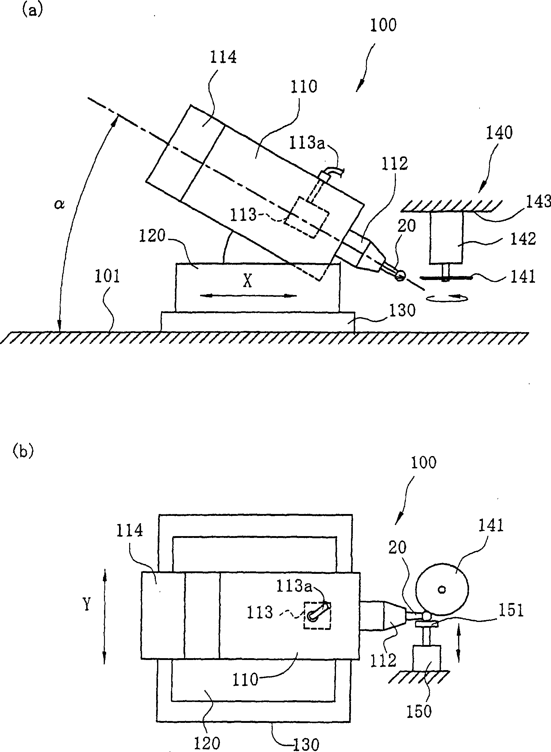
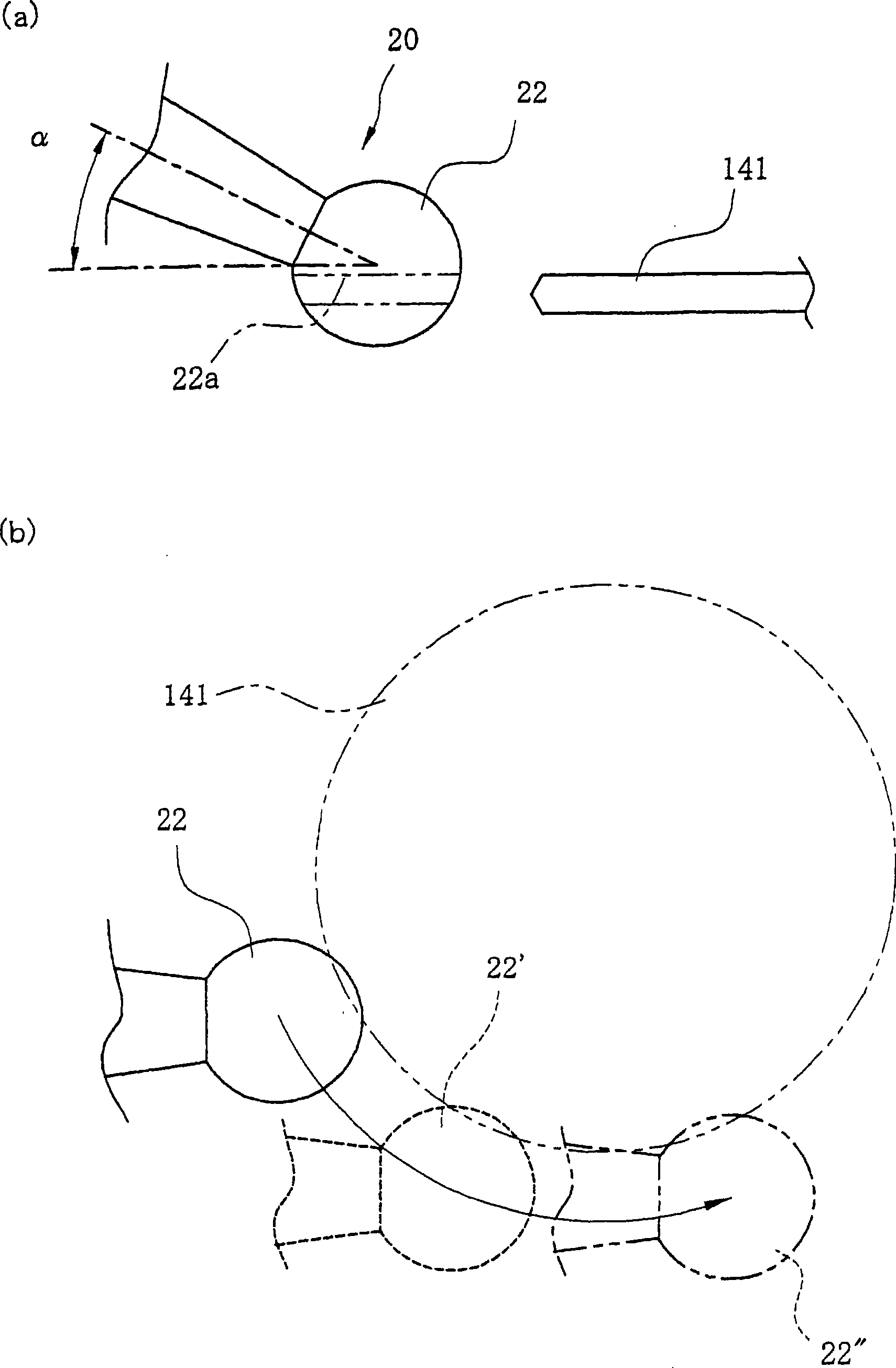
[0023] figure 1 It is a schematic diagram which shows the main part structure of the manufacturing apparatus of the medical cutting tool of this invention, (a) is a front view, (b) is a top view. Hereinafter, a medical cutting tool will be described using a steel bur as an example. As shown in the figure, the medical cutting tool manufacturing apparatus 100 of the present invention includes a main shaft part 110, a main shaft support part 120 supporting the main shaft part 110, an XY table 130 for moving the main shaft support part 120 in the X and Y directions, and a rotary The grindstone unit 140 is constituted.

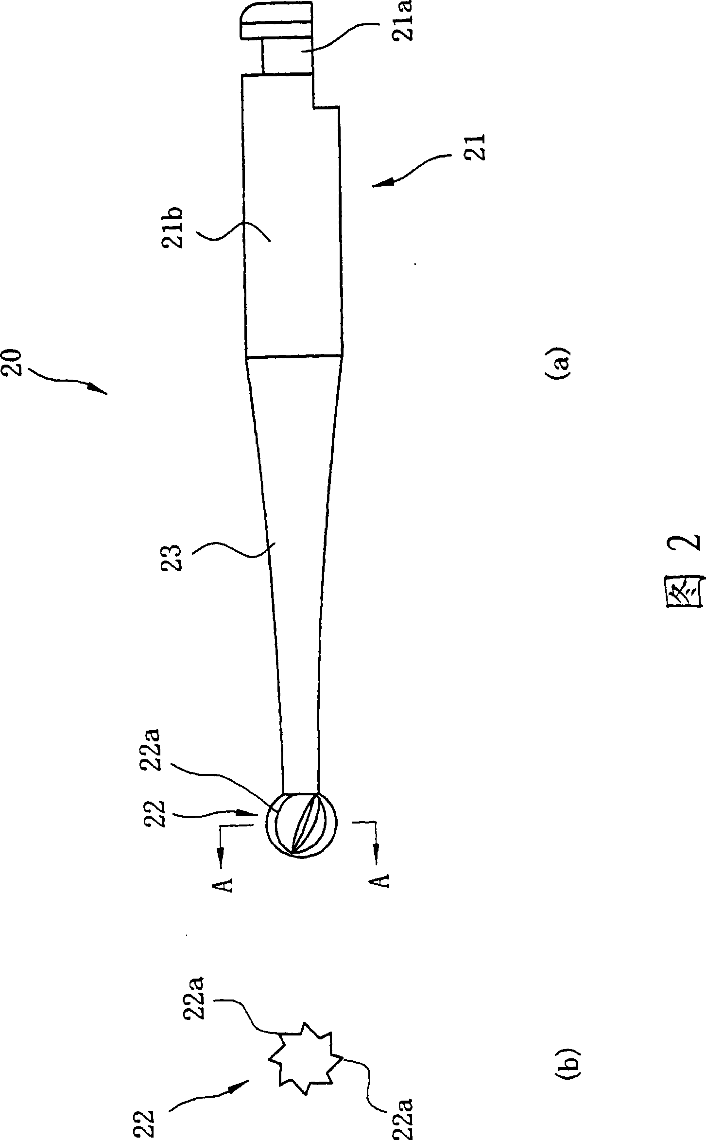
[0024] The main shaft part 110 has a chuck 112, and the clamping device 113 formed inside the main shaft part 110 is driven by the high-pressure fluid supplied from the pipe body 113a, and can attach and detach the steel drill bit 20 as a workpiece.

[0...


PUM


Abstract

The invention provides a medical cutting tool manufacturing apparatus, which can form cutting blades to the top face with a simple structure, and a manufacturing method for the same are provided. The medical cutting tool manufacturing apparatus of the present invention, which manufactures a medical cutting tool such as a steel bar having a plurality of cutting blades at the tip of a working section, includes a main shaft, which includes a chuck that holds the steel bar in a freely detachable manner; a main shaft support, which holds the main shaft allowing change in a slant angle of the main shaft; an XY table, which freely moves the main shaft support in X and Y axis directions; and a rotatable disc whetstone, which forms the cutting blades in the working section of the medical cutting tool held by the chuck. The whetstone has a structure within the horizontal plane (XY plane).

Description

technical field [0001] The present invention relates to a dental cutting tool or a surgical drill with an inclined cutting edge at the working part of the front end of a carbon drill, a steel drill, a P-type root canal drill (Peeso reamer) or a G-type drill (Gates drill). A manufacturing technique of a medical cutting tool such as a needle, in particular, relates to a manufacturing device and a manufacturing method of a medical cutting tool suitable for forming a cutting edge at a working portion at the tip. Background technique [0002] Image 6 It is a figure explaining the conventional manufacturing apparatus and manufacturing method of manufacturing the medical cutting tool which has the inclined cutting edge in the working part of the front-end|tip, such as a steel drill. [0003] A steel drill 10 as a workpiece is held on a chuck 13 positioned at the front end of a spindle portion 12 fixed to a bed 11 of the processing machine. The inside of the main shaft part 12 has...

Claims


Application Information

Patent Timeline
Patent Type & Authority Applications(China)
IPC IPC(8): B24B3/00A61C3/02A61B17/16B23Q1/62B23Q1/64B24B3/60
CPCB24B19/04A61C3/02B24B3/065B24B41/066A61C1/06
Inventor 塩入睦纪手塚智加藤一明
Owner MATSUTANI SEISAKUSHO CO LTD
Why Eureka
Try Eureka