

Helicopter rotor operation method and system
A helicopter rotor and control system technology, applied in the field of helicopter control, can solve the problems of actuators not working normally, no measurement and control scheme, no transmission mechanism, etc., shorten the development cycle, improve safety and survivability, and facilitate The effect of integration
Inactive Publication Date: 2010-11-10
NANJING UNIV OF AERONAUTICS & ASTRONAUTICS
View PDF0 Cites 24 Cited by
- Summary
- Abstract
- Description
- Claims
- Application Information
AI Technical Summary
Problems solved by technology
In this design scheme, the actuator is located near the tip of the blade in the radial direction, where the centrifugal force is huge, and the actuator will not work normally under this action; There is no transmission mechanism between the actuators; the pitch change spring of the blade root is similar to the pitch change rod of a conventional helicopter, which will also produce a large waste resistance; in addition, the plan does not mention the corresponding measurement and control plan, so it is considered that the flap control is open loop control
Method used
View moreImage
Smart ImageViewing Examples

Examples
Embodiment Construction
Login to View More PUM
 Abstract
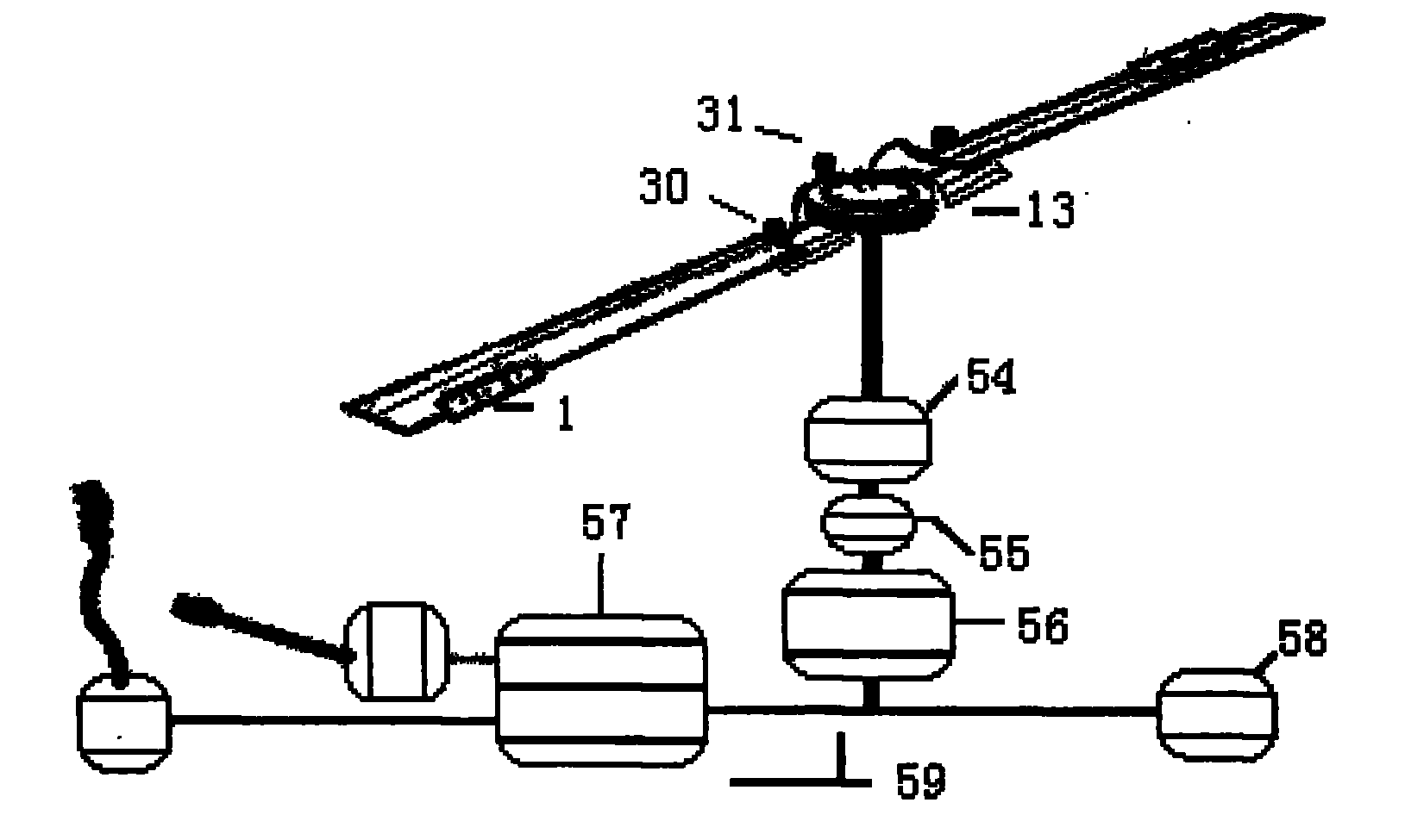
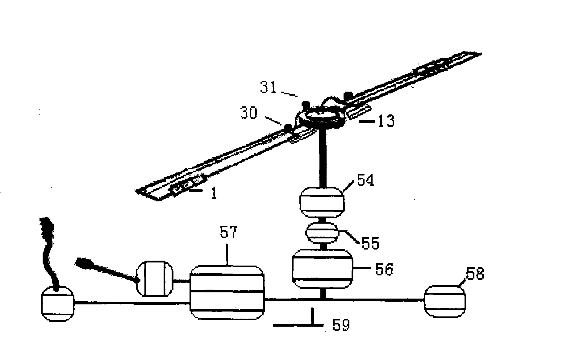
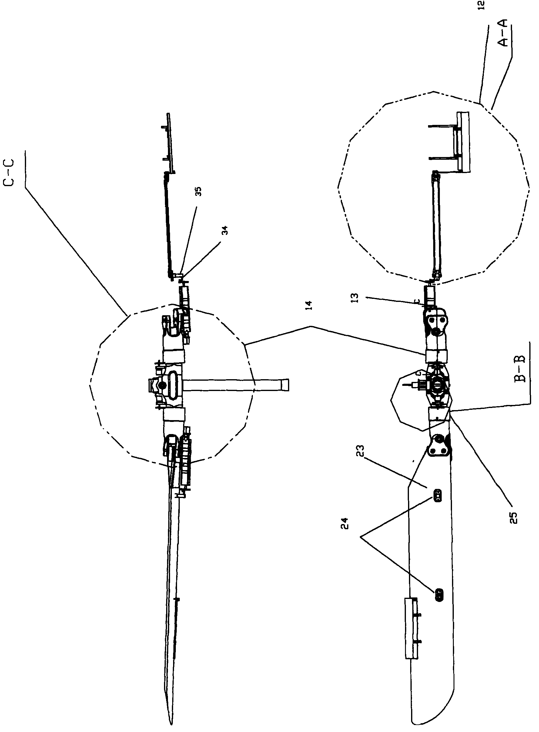
The invention relates to a control method and a system of a helicopter rotor, which belongs to the technical field of helicopter operation. The control method is characterized in that the distance changing of a blade is realized by adopting an actuator positioned on the stinger of each propeller boss to drive a flap positioned at the rear edge of the blade, so as to realize the control of a rotorsystem. The system comprises a demountable flap (1) installed at rear edge of the blade, torque soft propeller bosses (14), an actuator (13) installed on the stinger of torque soft propeller bosses, a flap control mechanism (1) with one end being connected with actuator (13) and the other end thereof being connected with the flap (1), and a test control system (59). The control method and the system have the advantages that the screw piston of each blade can be independently controlled, the structure is simple, the weight is light, the controllability is good, and the reliability and the security are high.
Description
Helicopter rotor control method and system Technical field The invention relates to a helicopter rotor control method and system, belonging to the technical field of helicopter control. technical background Due to its unique flight characteristics, the helicopter can hover, vertically lift, and fly in any direction, making it unique in the large family of aircraft; the reason why the helicopter has this ability is mainly due to the rotor and its operation. system. The rotor and its control system are the key components of the helicopter, which have an important impact on the performance, control stability and flight safety of the helicopter. Existing helicopter generally realizes helicopter manipulation by indirectly manipulating the automatic tilter, and the basic principle of its work is shown in the introduction in the reference: (Bosi. Russian Helicopter founder--Yuriev. , 2001(3).5~6.). The automatic tilter is composed of a rotating ring and a non-rotating ring. T...
Claims
Login to View More Application Information
Patent Timeline
 Patent Type & AuthorityPatents(China)
IPC IPC(8): G05D1/08B64C27/615B64C11/44G01B11/26
Inventor陆洋夏鹤鸣王浩文高正肖荣
OwnerNANJING UNIV OF AERONAUTICS & ASTRONAUTICS