Method for driving backlight source of liquid crystal display apparatus and backlight source

A technology of a liquid crystal display device and a driving method, applied in the field of backlight sources, can solve the problems of unstable brightness, high implementation cost, and cannot effectively solve smearing, etc., and achieve the effects of improving display effect, avoiding smearing phenomenon, and improving display effect.

Active Publication Date: 2009-03-04
K TRONICS (SUZHOU) TECH CO LTD +1
View PDF1 Cites 30 Cited by
  • Summary
  • Abstract
  • Description
  • Claims
  • Application Information

AI Technical Summary

Problems solved by technology

The light source used in this technical solution is CCFL, which is a commonly used light source for liquid crystal displays. However, CCFL is a linear light source with a large size. Due to its size limitation, the number of scanning lamps cannot be too large, so it cannot be properly combined with Each row of pixel units corresponds, which cannot effectively solve the problem of smearing
In addition, this technical solution uses a mechanical structure to rotate to scan the backlight. The backlight will change with...

Method used


Image

  • Method for driving backlight source of liquid crystal display apparatus and backlight source
  • Method for driving backlight source of liquid crystal display apparatus and backlight source
  • Method for driving backlight source of liquid crystal display apparatus and backlight source

Examples


Embodiment Construction

[0025] Embodiment of driving method for backlight source of liquid crystal display device

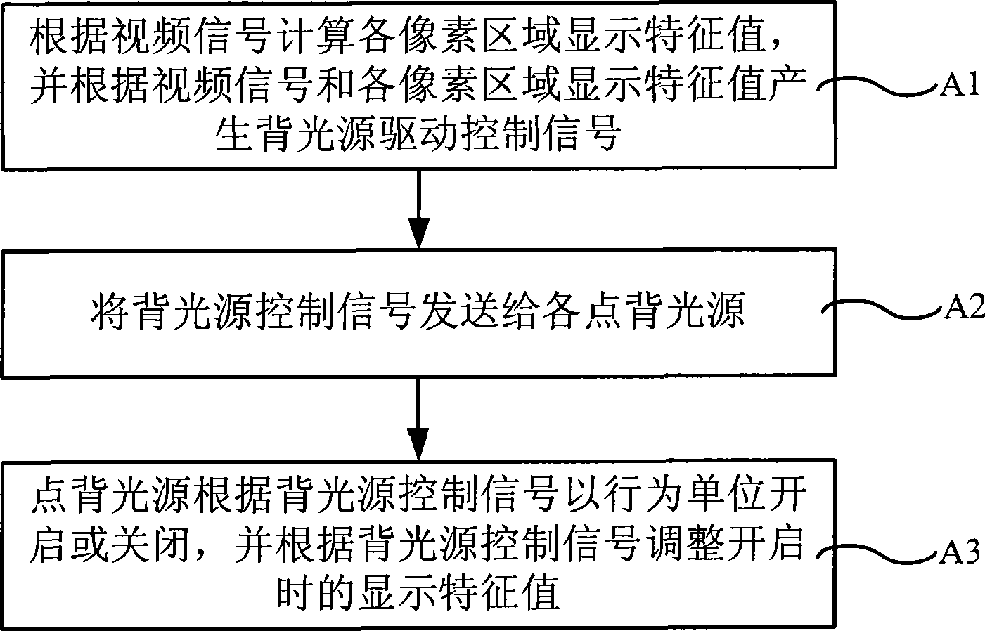
[0026] Such as figure 1 Shown is the flow chart of a specific embodiment of the method for driving the backlight source of a liquid crystal display device according to the present invention. The driving process of the backlight source in this embodiment is carried out synchronously with the process of driving pixels to display images. After the video signal is input into the control device, horizontal data signals and vertical data signals are generated. Scan signal, control the display of the pixel on the liquid crystal display panel, meanwhile, the driving process of the backlight source of the present embodiment also begins to carry out, comprises the following steps:

[0027] Step A1, the control device calculates the display feature value of each pixel area according to the video signal, the display feature value includes at least a color threshold and / or brightness value, and gene...


PUM


Abstract

The invention relates to a backlight source drive method and a backlight source of a liquid crystal display, and the backlight source drive method comprises: a display characteristic value of each pixel region is computed according to a video signal, and a backlight source control signal is generated according to the display characteristic value and the video signal; the backlight source control signal is transmitted to each point backlight source; the point backlight source controls the opening or closing of an action unit and adjusts the display characteristic value when opening according to the control signal. The backlight source comprises a backlight source lattice which consists of the point backlight sources that are arranged correspondingly to a pixel unit and a control device which is used for controlling the opening or closing of the point backlight sources, wherein, the point backlight sources are colored point backlight sources with controllable colors, and the control device is respectively connected with each point backlight source and used for controlling the opening or closing of each point backlight source as well as the color or the brightness when opening. The backlight source drive method and the backlight source can effectively avoid the trailing smear phenomenon, raise the image contrast ratio and have more vivid color and better display effect, and can simultaneously lower the energy consumption of the backlight sources.

Description

technical field [0001] The invention relates to a method for driving a backlight source of a liquid crystal display device and a backlight source, in particular to a method for driving a backlight source suitable for a thin film transistor liquid crystal display and a backlight source for implementing the driving method. Background technique [0002] Liquid crystal display technology is gradually replacing the traditional cathode ray tube (CRT) display technology with its many advantages in display effect. Liquid crystal display displays images by switching the light output through the pixel matrix. The pixels themselves do not have the ability to actively emit light. The backlight system needs to provide efficient and uniform light source transmission to achieve light output. This is different from the scanning imaging method of CRT. , so the liquid crystal display will not produce a flickering feeling. [0003] However, the driving method of liquid crystal displays, espec...

Claims


Application Information

Patent Timeline
IPC IPC(8): G09G3/34G09G3/36G09G3/20H05B37/02G02F1/133
Inventor 冷长林张亮王延峰商广良
Owner K TRONICS (SUZHOU) TECH CO LTD
Why Eureka
Try Eureka