Initiative reciprocating type zero-tillage anti-blocking unit body

A reciprocating, unitary technology, applied in the field of agricultural machinery, can solve the problems of high vibration and noise of the machine, poor safety performance, poor anti-blocking ability, etc., and achieve the effect of clearing accumulation blockage, easy disassembly and assembly, and preventing blockage

Inactive Publication Date: 2009-03-11
CHINA AGRI UNIV
View PDF4 Cites 14 Cited by
  • Summary
  • Abstract
  • Description
  • Claims
  • Application Information

AI Technical Summary

Problems solved by technology

[0005] The purpose of the present invention is to overcome the poor anti-blocking ability of the passive anti-blocking device in the background technology, which is only suitable for the situation where the surface straw coverage is small and the power-driven anti-blocking device has high cutter shaft speed, large machine vibration noise, and safety. Poor performance and other problems require that the anti-blocking unit configured on the no-tillage planter can effectively prevent the clogging of the opener, improve the quality of planting, the working efficiency of the machine, and benefit the growth of crop seedlings. Provide an active reciprocating no-tillage anti-blocking unit The body is characterized in that the active reciprocating no-tillage anti-blocking unit body is composed of two parts: a ditching device and a blocking removal device. The ditching device of the shaped structure, the upper fixing plate 7 and the lower fixing plate 2 of the blocking removal device are respectively positioned through the positioning holes 9 and fixed on the right side of the opener shovel handle 8 with bolts up and down, and the upper sprocket 12 is assembled On the long axis 6, the upper bearing sleeve 14 is affixed to the right side of the upper fixed plate 7, and a pair of upper bearings 13 are installed in the upper bearing sleeve 14, and the long axis 6 passes through a pair of upper bearings 13, the upper bearing sleeve 14 And the upper bearing end cover 16 is installed on the upper fixed plate 7, there is a washer between the upper sprocket 12 and the upper bearing 13, so that there is a gap between the upper sprocket 12 and the upper bearing 13, and the upper shaft positioning nut 17 is assembled on the long axis 6. The gap between its bottom surface and the upper bearing end cover 16 is 0.1-0.2 mm to prevent the axial movement of the long shaft 6. The upper shaft positioning lock nut 24 is assembled on the long shaft 6 on the right side of the upper shaft positioning nut 17, and the upper shaft is locked. The shaft positioning nut 17, the lower sprocket 19 are assembled on the short shaft 3, the lower bearing cover 21 is affixed to the right side of the upper fixed plate 7, the lower bearing 20 is installed in the lower bearing cover 21, and the short shaft 3 passes through the lower bearing 20 and the lower bearing cover 21 are installed on the lower fixed plate 2, there is a washer between the lower sprocket 19 and the lower bearing 20, so that there is a gap between the lower sprocket 19 and the lower bearing 20, and the lower shaft positioning nut 22 is assembled on the short shaft 3, The gap between its bottom surface and the lower bearing cover 21 is 0.1-0.2mm, to prevent the axial movement of the short shaft 3, the lower shaft positioning lock nut 23 is assembled on the short shaft 3 on the right side of the lower shaft positioning nut 22, and locks the lower shaft positioning nut 22 , Weld a finger 5 on each section of the chain 4 to form a finger chain, the finger chain is connected with the upper sprocket 12 and the lower sprocket 19 to form a blocking removal part, and the long axis 6 passes through the left key 11 with a coupling It is connected with the long axis of the active reciprocating no-tillage anti-blocking unit adjacent to the left side, and the long axis 6 is connected with the long axis of the active reciprocating no-tillage anti-blocking unit adjacent to the right side with a coupling through the right key 18, Input and output power, drive the deblocking parts that finger chain, upper sprocket 12 and lower sprocket 19 form to carry out active reciprocating type deblocking operation, perhaps install large sprocket and on major shaft 6 by left key 11 or right key 18 The large sprocket on the side of the gearbox constitutes a chain transmission mechanism to transmit power to the blocking removal parts

Method used


Image

  • Initiative reciprocating type zero-tillage anti-blocking unit body
  • Initiative reciprocating type zero-tillage anti-blocking unit body
  • Initiative reciprocating type zero-tillage anti-blocking unit body

Examples


Embodiment Construction

[0014] The concrete structure of the embodiment of the present invention and working process are described below in conjunction with accompanying drawing:

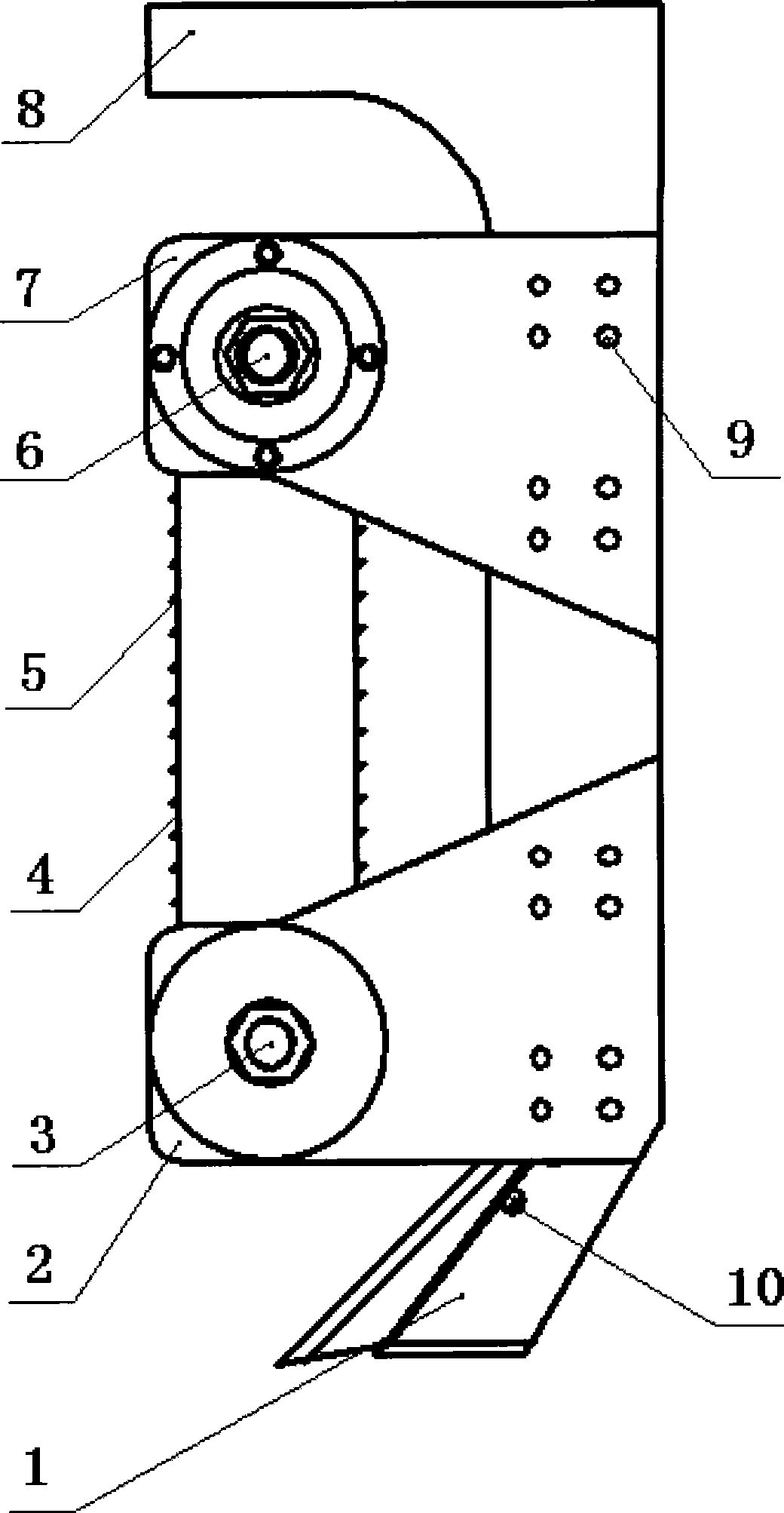
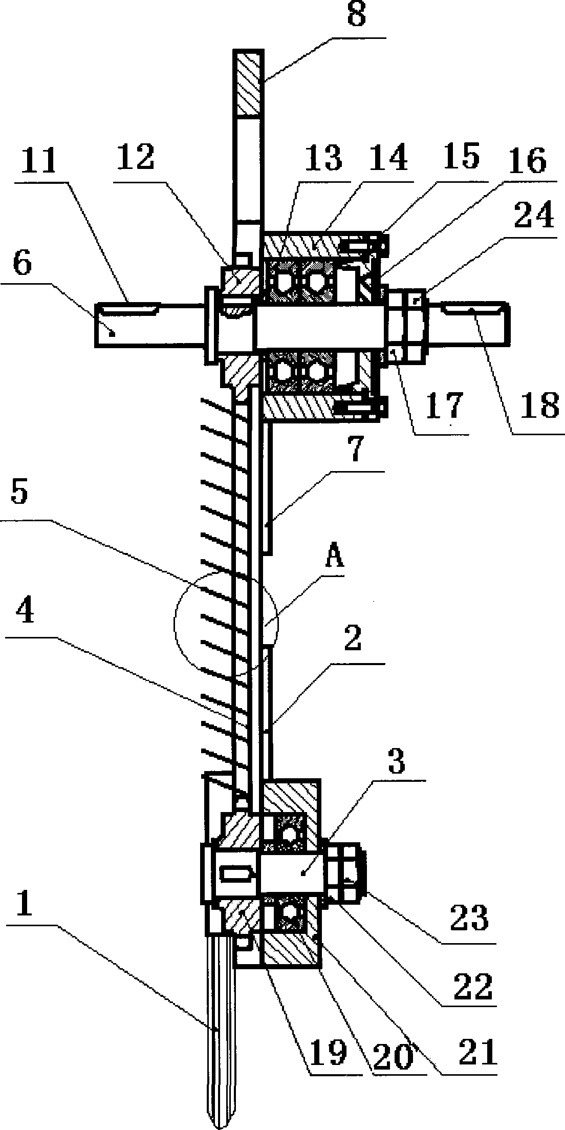
[0015] Such as figure 1 , figure 2 The shown active reciprocating no-tillage anti-blocking unit body is mainly composed of ditch opener 1, ditch opener shovel handle 8, upper fixing plate 7, lower fixing plate 2, short axis 3, long axis 6, chain 4, finger 5, Upper sprocket 12, lower sprocket 19 etc. constitute. Wherein the ditcher 1 and the ditch opener shovel handle 8 are connected together by the hexagon socket head bolt 10, and the left half of the whole structure leaves 2 / 3 gaps to form a concave structure. The upper fixed plate 7 and the lower fixed plate 2 are respectively positioned through the positioning hole 9 and fixed on the upper and lower parts of the right side of the opener shovel handle 8 with bolts up and down. The long axis 6 passes through the upper bearing 13, the upper bearing sleeve 14, The faste...


PUM


Abstract

The invention discloses an active reciprocating no-tillage anti-blocking unit, and belongs to the technical field of agricultural machinery. The structure of the unit consists of a furrowing device and an anti-blocking device. A furrow opener is fixed at the lower end of a shovel shaft of the furrow opener to form the furrowing device with concave structure. The anti-blocking device consists of an upper retaining plate and a lower retaining plate which are fixed on the shovel shaft of the furrow opener face to face, as well as a long shaft, a short shaft, an upper chain wheel, a lower chain wheel, a plectrum chain and the like. The anti-blocking plectrum chain is provided above the furrow opener, and long shafts of all anti-blocking unit bodies are connected by couplings. The active reciprocating no-tillage anti-blocking unit has the advantages: the plectrum chain is provided above the furrow opener, which is favorable for cleaning the deposit during furrowing by the furrow opener, reducing the seeding resistance and is good for the trafficability characteristic of a machine; power-drive blockage prevention is adopted, which enhances the blockage prevention effect obviously by regulating the rotary speed of the plectrum chain device; and the unit bodies are connected by the couplings, can realize the adjustability of the seeding row spacing and are applicable to operations at various areas. The active reciprocating no-tillage anti-blocking unit is applicable to the no-tillage seeding machine for wheat and corn.

Description

technical field [0001] The invention belongs to the technical field of agricultural machinery and relates to an active reciprocating no-tillage anti-blocking unit body applied to a seeder. technical background [0002] Conservation tillage is an advanced agricultural farming method that implements no-tillage and less-tillage on farmland, reduces soil tillage as much as possible, and covers the surface with crop stalks and residues to reduce soil wind and water erosion, and improve soil fertility and drought resistance. The core issue of demonstration and popularization of conservation tillage technology is suitable no-tillage sowing equipment, especially the successful development of no-tillage sowing equipment suitable for different types of agricultural areas will be of great significance. The main technical problem of my country's wheat and corn no-tillage planters is the straw and stubble treatment device. At present, domestic research on anti-blocking technology of no-t...

Claims


Application Information

Patent Timeline
Patent Type & Authority Applications(China)
IPC IPC(8): A01C5/06
Inventor 何进李洪文张喜瑞王庆杰张学敏李问盈李慧
Owner CHINA AGRI UNIV
Why Eureka
Try Eureka