Chamber type automatic duplicate supply converting switch

A technology of dual power conversion and power switching, which is applied to electric switches, emergency power arrangements, circuits, etc., can solve the problems of reducing the possibility of simultaneous power feeding, the contacts are prone to heating and burning, and the contact resistance increases, etc., to achieve Eliminate safety hazards, increase insulation performance and arc extinguishing performance, and prolong service life

Inactive Publication Date: 2009-03-11
南通成平建设开发有限公司
View PDF1 Cites 27 Cited by
  • Summary
  • Abstract
  • Description
  • Claims
  • Application Information

AI Technical Summary

Problems solved by technology

[0003] Chinese patent application 200610154471.3 discloses an outdoor high-voltage dual-power vacuum circuit breaker. This type of vacuum circuit breaker is equipped with a high-voltage dual-power conversion device consisting of a chained double-throw isolating switch on the vacuum circuit breaker. Although this method realizes high-voltage There are electrical interlocking and mechanical interlocking when the dual power supply is automatically switched, which reduces the possibility of two high-voltage feeds at the same time. It is an ideal high-voltage dual power switching device at present, but there are still drawbacks. In the external environment, with the increase of the number of times and time of use, the surface of the contact will continue to oxidize, resulting in an increase in the resistance of the contact and a decrease in the conductivity, and the contact is prone to heat and burnout.

Method used


Image

  • Chamber type automatic duplicate supply converting switch
  • Chamber type automatic duplicate supply converting switch
  • Chamber type automatic duplicate supply converting switch

Examples


Embodiment 1

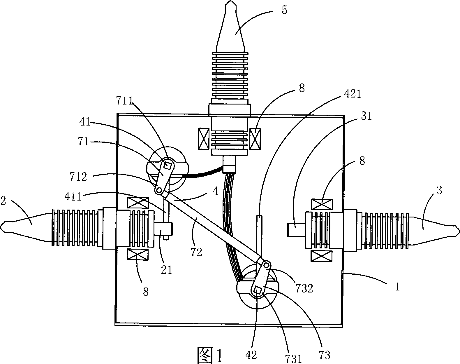
[0026] Fig. 1 is a structural schematic diagram of the first structure of the present invention, showing the first specific embodiment of the present invention.

[0027] This embodiment is a box-type automatic dual power supply switch, including a box body 1, three main power supply terminal posts 2, three backup power supply terminal posts 3, three load terminal posts 5 arranged on the box body 1, and Power switching mechanism 4; the power switching mechanism 4 includes a main switching spindle 41 and an auxiliary switching spindle 42, and the main switching spindle 41 is provided with three main switching contact knives for switching with the main power terminal 2 411, the auxiliary switching shaft 42 is provided with three auxiliary switching contact knives 421 for switching with the backup power terminal 3, and the main switching main shaft 41 and the auxiliary switching shaft 42 are linked through the interlocking interaction mechanism 7. The main throwing and cutting con...

Embodiment 2

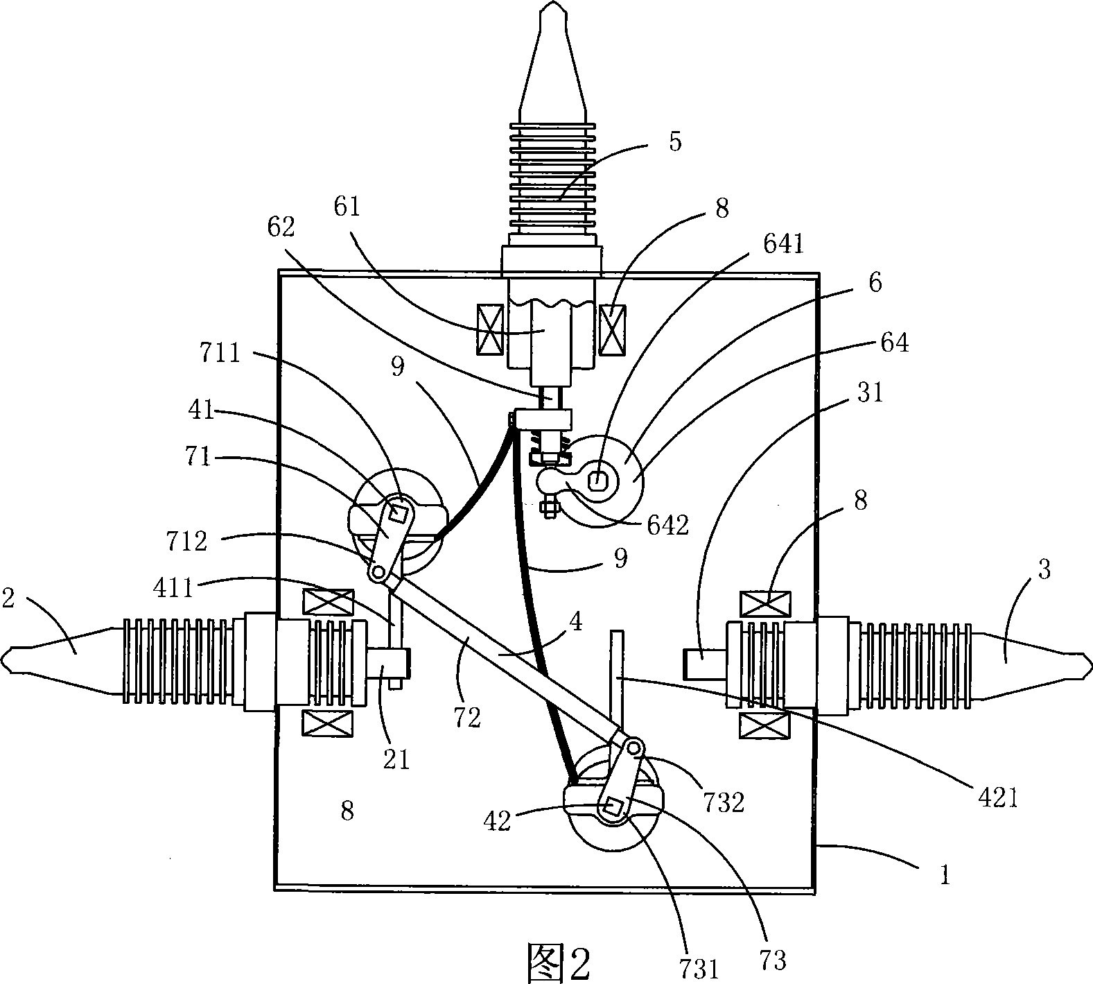
[0037] Fig. 2 is a schematic structural diagram of the second structure of the present invention, showing a second specific implementation manner of the present invention.

[0038] This embodiment is basically the same as Embodiment 1, the difference is that: the transfer switch also includes a three-phase vacuum circuit breaker device 6; the three-phase vacuum circuit breaker device 6 includes three vacuum interrupters 61, three dynamic Contact 62, three static contacts, voltage transformer 9 and corresponding operating mechanism 64; 411 and a corresponding auxiliary switching contact knife 421 are electrically connected by a soft connection 9, and the static contact is electrically connected to the load terminal 5; the operating mechanism 64 includes a drive spindle 641 for powering the movable contact 62, And a transmission rod 642 for connecting the drive shaft 641 and the movable contact 62 . The operating mechanism 64 of the three-phase vacuum circuit breaker device 6 i...

Embodiment 3

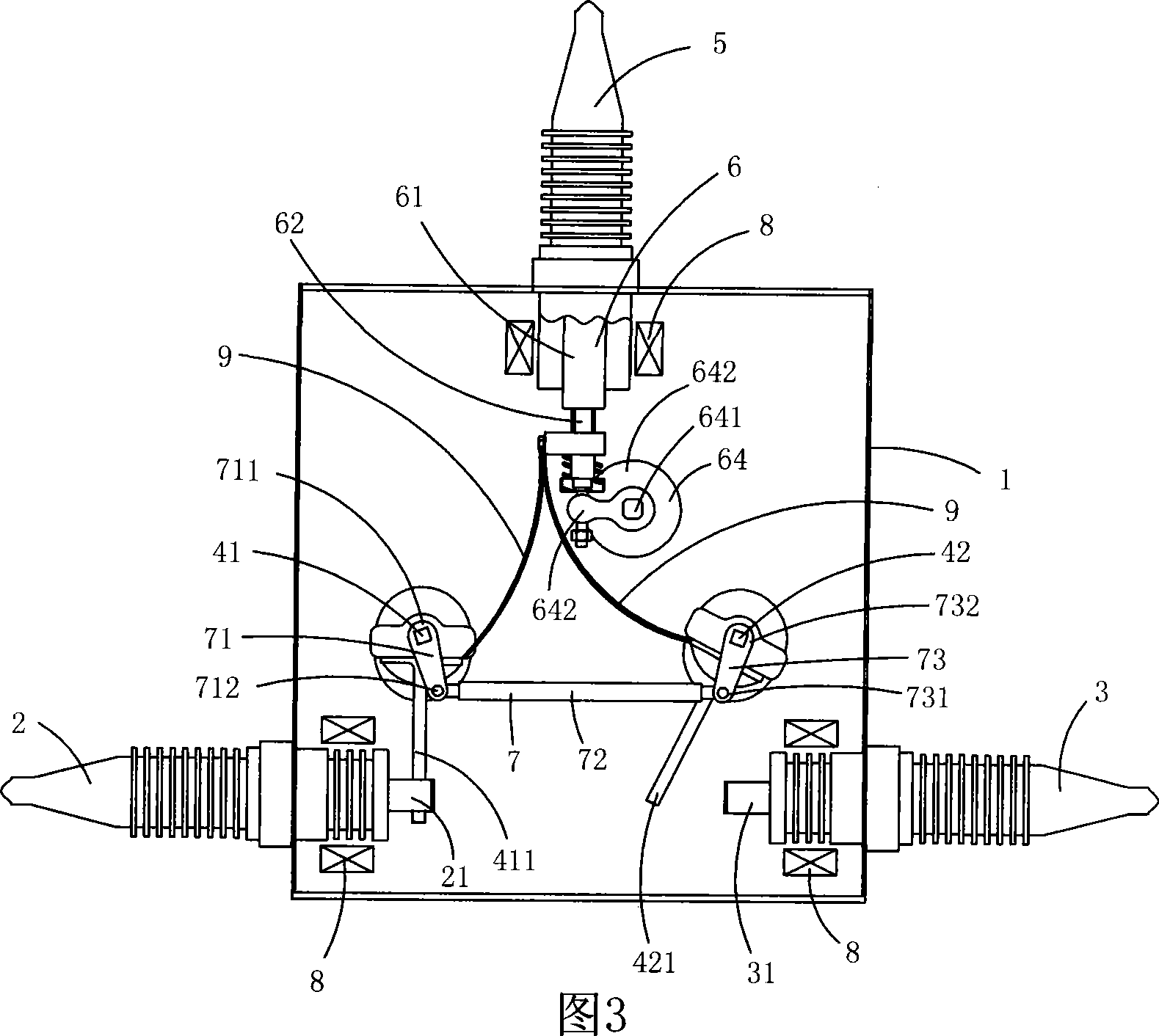
[0043] Fig. 3 is a schematic structural diagram of the third structure of the present invention, showing a third specific implementation manner of the present invention.

[0044] This embodiment is basically the same as Embodiment 2, except that: the main switching spindle 41 is arranged below the main power terminal 2, and the auxiliary switching axis 42 is also arranged under the backup power terminal 3; The fixed end 711 of the first link 71 and the fixed end 732 of the third link 73 are located on the same side of the second link 72 .

[0045] This embodiment has the advantages of compact structure and less occupied space.


PUM


Abstract

The invention discloses a box type automatic double-power-supply transfer switch which comprises a box body, three main power supply binding posts which are arranged on the box body, three spare power supply binding posts, three load binding posts and a power supply transferring mechanism, wherein the power supply transferring mechanism comprises a main transferring shaft and an auxiliary transferring shaft, three main switching contact knifes which are used for switching the main power supply binding posts are arranged on the main transferring shaft, three auxiliary switching contact knifes which are used for switching the auxiliary power supply binding posts are arranged on the auxiliary transferring shaft, and the main transferring shaft and the auxiliary transferring shaft are linked by an interlocking interactive mechanism. The invention transfers double power supplies by linking the two shafts and has the advantages of compact structure and small volume.

Description

technical field [0001] The invention belongs to the technical field of high-voltage electric switches, and in particular relates to a box-type automatic dual-power switch. Background technique [0002] At present, in order to improve the reliability of power supply, a large number of dual power supply lines (two power supply lines, generally one power system line and one self-contained line) are used in the power supply system. When the power supply of one line fails, the other line supplies power. . For this reason, control devices are needed, and no less than two high-voltage switchgears should be used indoors, and no less than two high-voltage switches on poles should be used outdoors, so as to realize the requirements of selecting power supply lines. This control method not only increases the user's equipment and operating costs, but also poses hidden dangers of power supply accidents. For two or more high-voltage switchgear / column-mounted high-voltage switches, it is ...

Claims


Application Information

Patent Timeline
Patent Type & Authority Applications(China)
IPC IPC(8): H01H19/38H01H9/26H02J9/06
CPCY02B70/30Y04S20/20
Inventor 黄勤飞
Owner 南通成平建设开发有限公司
Why Eureka
Try Eureka