
Device for preventing sway of suspended load

A load and swing angle technology, applied in the direction of load suspension components, motor control, transportation and packaging, etc., can solve the problems of complicated calculations, difficult to set swing angle detectors, etc., and achieve the effect of easy adjustment of control

Active Publication Date: 2009-03-11
YASKAWA DENKI KK
View PDF3 Cites 10 Cited by
  • Summary
  • Abstract
  • Description
  • Claims
  • Application Information

AI Technical Summary

Problems solved by technology

[0017] However, generally in an unloader or a bridge crane, etc., it is difficult to install the swing angle detector 229 in the structure of the equipment.
[0018] In addition, when calculating the swing angle of the sling, the calculation of friction resistance removal requires the weight and friction coefficient of the trolley or hoisted load, so the calculation is complicated
[0019] Moreover, in order to obtain the angular frequency ω e It is necessary to measure the length Le of the lifting sling, and the calculation is still complicated

Method used


Image

  • Device for preventing sway of suspended load
  • Device for preventing sway of suspended load
  • Device for preventing sway of suspended load

Examples


Embodiment 1

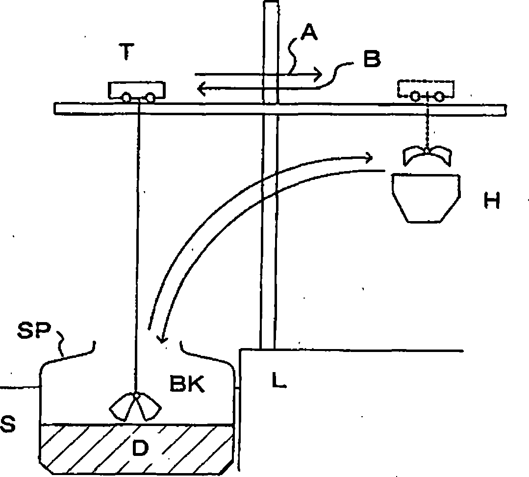
[0043] figure 1 It is a device schematic diagram of an unloader as an example of the object of the present invention.

[0044] figure 1 Among them, T is a trolley, A is for land, B is for ocean, H is hopper, SP is ship, BK is grab, S is ocean, L is land, and D is raw material.

[0045] In the figure, an unloader is installed on the land L facing the sea S, and a trolley T is installed at a specified height from the land L, and the built-in motor can horizontally reciprocate between the sea and the land.

[0046] A rope hoisting motor is also mounted on the trolley T, and a grab bucket BK is mounted on the front end of the rope.

[0047] The trolley moves to the top of the ship SP close to the land, lowers the grab bucket BK and grabs the load of the ship by the grab bucket BK, that is, the raw material D, then rolls up the sling to lift the grab bucket BK, and at the same time moves from the ocean S to the land L, and moves to the land Throw raw material D into the hopper...


PUM


Abstract

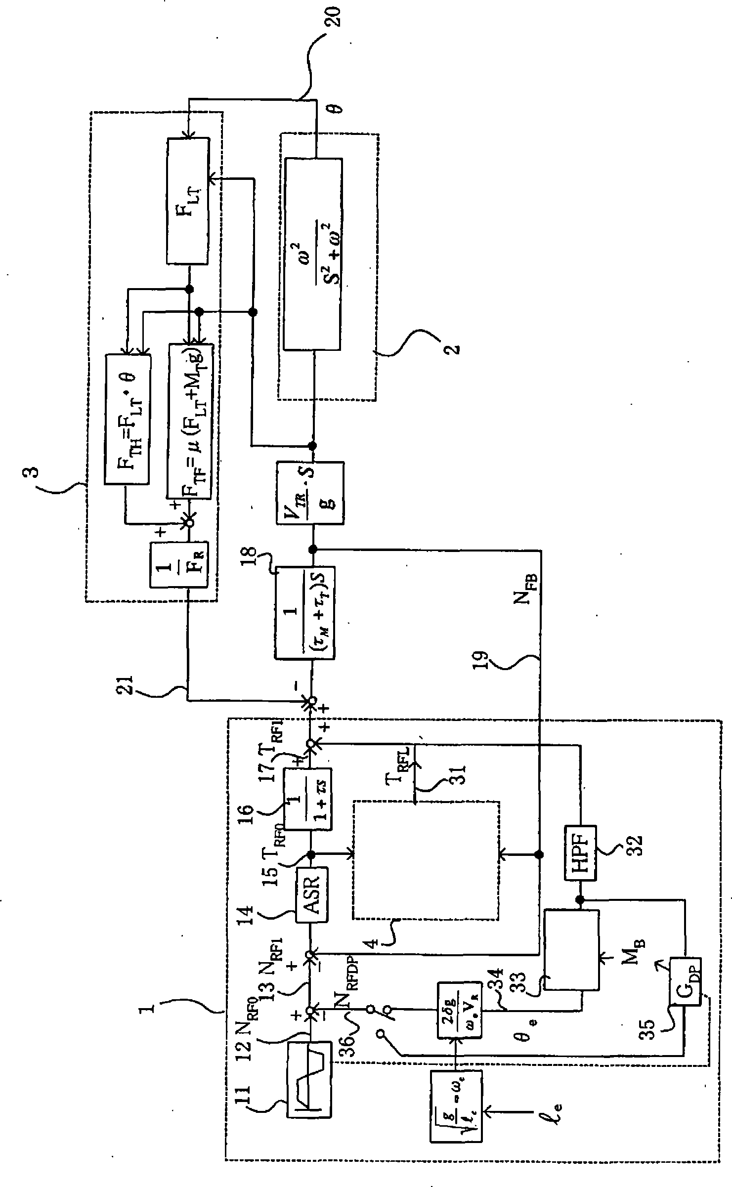
A device for preventing sway of a suspended load, which does not require complex calculation for removing a frictional resistance component. The device has a speed control device (14) for outputting a torque command based on a speed command, a torque command filter (16), and a load torque observer (4) for estimating load torque. The device outputs a value formed by adding a load torque estimation signal to an output of the torque command filter (16). The device also has a bypass filter (32) for outputting a signal TRFLHPF obtained by removing a frictional resistance component from the load torque estimation signal and also has a sway angle calculator (33) for outputting an estimated calculated value theta e of sway angle obtained by multiplying a sway angle calculator factor to the output signal TRFLHPF. A value inputted to the speed control device (14) is obtained by deducting a damping compensation signal NRFDP that is obtained by damping-compensating the estimated calculation value theta e of sway angle from a speed command created by a speed pattern creation circuit (11).

Description

technical field [0001] The present invention relates to a hoisting load swing prevention device for suppressing load swing during lateral movement of an unloader or bridge crane that unloads raw materials from a ship docked with iron ore or coal, for example. Background technique [0002] As a conventional swing prevention control technique for suspended loads, there is a "swing angle damping control method" described in Patent Document 1, for example. [0003] Figure 8 It is a block diagram of the traveling drive control device 220 described in patent document 1. [0004] Input the speed command signal of the speed command unit 221 into the linear command unit 222 to obtain the ramp speed command N RF0 . And, either one of the actually measured swing angle θ detected by the swing angle detector 229 of the rope and the swing angle Eθ calculated by the rope swing angle calculator 238 is selected by selecting the changeover switch 239 . Here, when the swing angle Eθ calcul...

Claims


Application Information

Patent Timeline
Patent Type & Authority Applications(China)
IPC IPC(8): B66C13/22B66C13/06H02P29/00
CPCB66C13/063B66C13/22
Inventor 池口将男柴田尚武长谷川肇
Owner YASKAWA DENKI KK
Learn More