Convection heat radiating device of led lamp

A light-emitting diode and heat dissipation device technology, which is applied in the cooling/heating device of the lighting device, the semiconductor device of the light-emitting element, the lighting device, etc., can solve the problems of fan damage and fan heat dissipation limitation, improve the heat dissipation effect and reduce the replacement of heat dissipation unit opportunity, the effect of significant cooling effect

Inactive Publication Date: 2009-03-18
陈世明
View PDF1 Cites 16 Cited by
  • Summary
  • Abstract
  • Description
  • Claims
  • Application Information

AI Technical Summary

Problems solved by technology

However, in light-emitting diode lamps, the installation environment may be outdoors (such as LED street lamps) or vehicle LED headlights, which are not as good as computer hosts. Dust, rain or dirt and oil will quickly damage the fan and emit light. D

Method used


Image

  • Convection heat radiating device of led lamp
  • Convection heat radiating device of led lamp
  • Convection heat radiating device of led lamp

Examples


Embodiment Construction

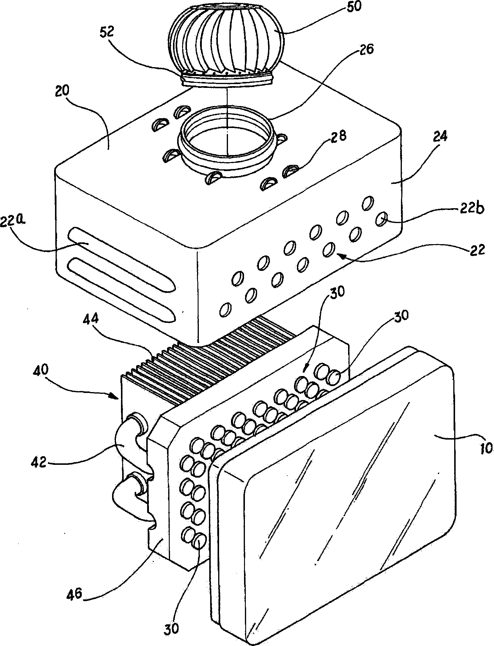
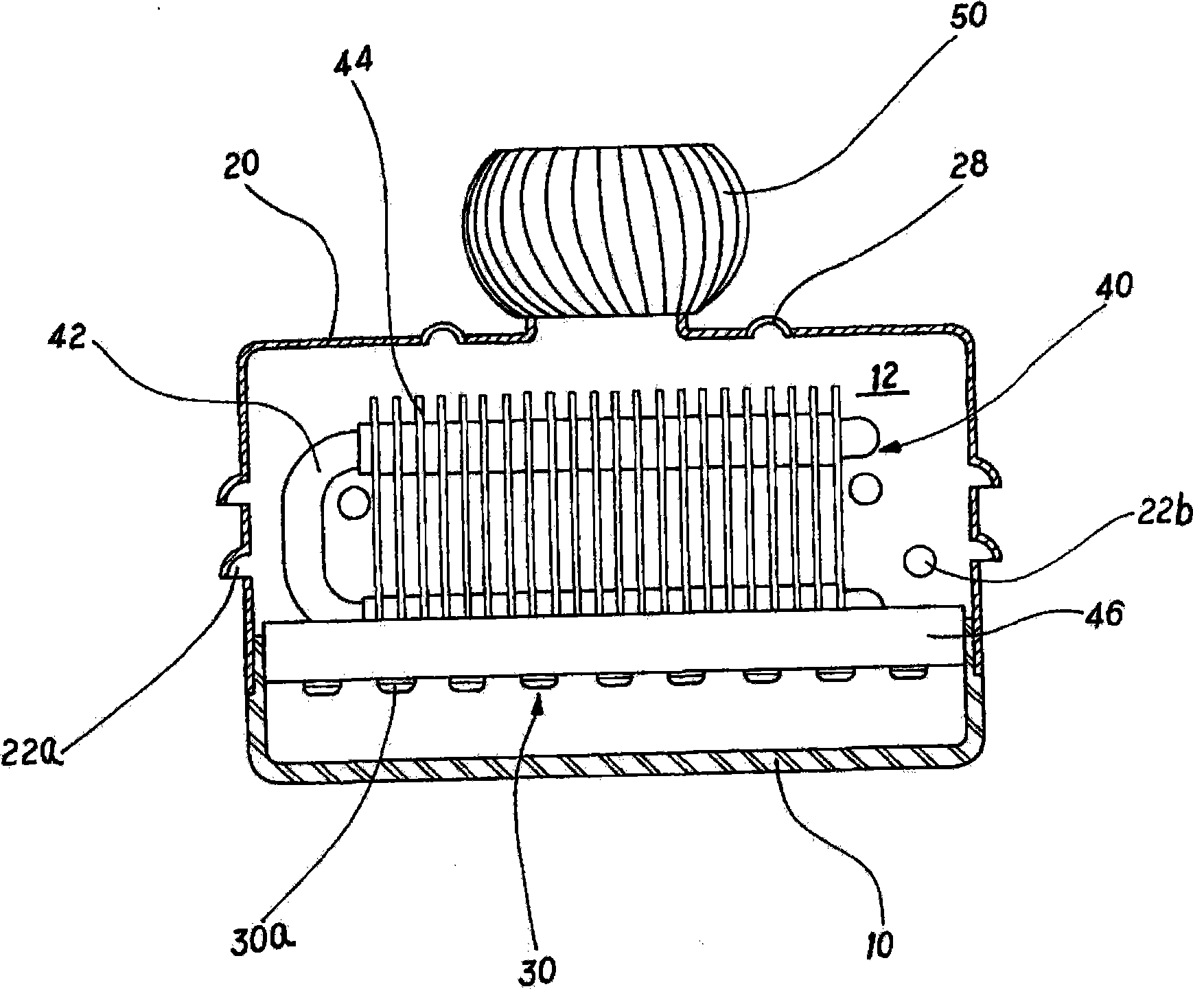
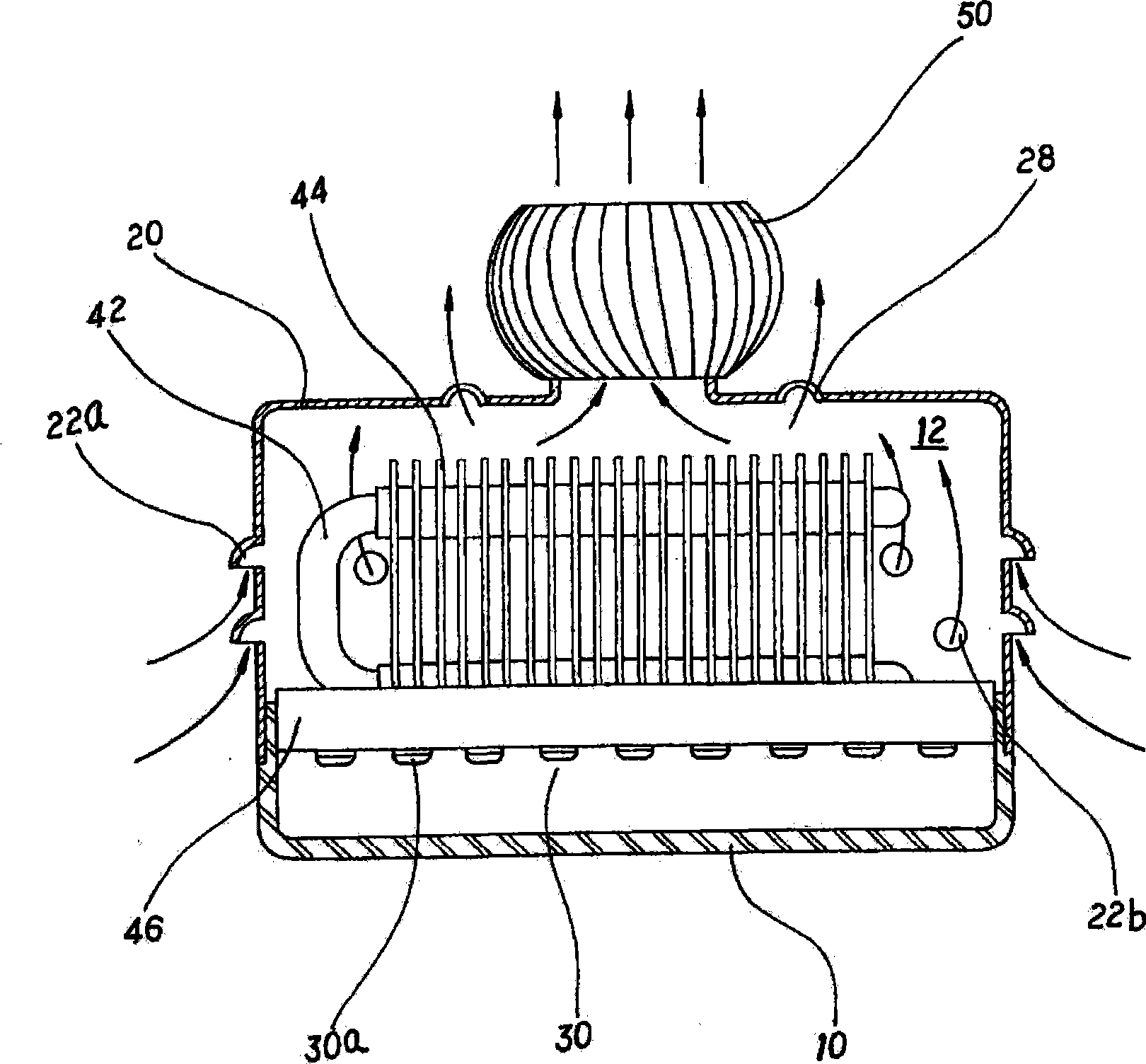
[0030] see figure 1 As shown, the lamp of the present invention has a light cover 10, the light cover 10 is a light-transmitting material, such as: plastic or glass formed, and combined with the cover body 20 to form an internal space 12, the light cover 10 will be arranged in front of the LED module 30 to evenly project the light emitted by the LED module 30 . The heat dissipation unit 40 can conduct heat conduction (heat dissipation) to the heat energy generated by the LED module 30, and is arranged at the rear end of the LED module 30. In this embodiment, the heat dissipation unit 40 includes a combination of a heat pipe 42, a heat sink 44, and a base 46. , but not limited to this combination, aluminum extrusion can also be used to form heat sinks. The LED modules 30 can be arranged in a variety of ways. The LEDs 30a can be directly planted on the base 46 of the cooling unit 40 as shown in the figure of this embodiment, or the LEDs 30a can be installed on a substrate first...


PUM


Abstract

The invention relates to a convection type radiating device of a light emitting diode lamp. The lamp utilizes a plurality of light emitting diodes as a luminous source; the light emitting diodes are arranged on a baseplate to combine with a base, or are directly arranged on a base of a radiating unit; a thermotube and a radiating rib are arranged on the base; a housing of the lamp is covered outside the components; any side of the housing can be provided with an air hole and an impeller; heat energy produced by the light emitting diodes permeates the base, the thermotube and the radiating rib and is transmitted to an inner space formed by the housing; external cold air is guided to the inner space through the air holes; and the heat energy existing in the inner space flows towards the cold end to drive the impeller to rotate and produce inner and outer convecting effect, thereby promoting the radiating efficiency of the lamp.

Description

technical field [0001] The invention relates to a heat dissipation device, in particular to a convection heat dissipation device applied to a light-emitting diode lamp. Background technique [0002] Compared with traditional light bulbs, light-emitting diodes have many advantages such as low power consumption, long component life, and fast response speed. They are small in size, and the current manufacturing process is becoming more and more mature. The configuration application becomes a very small or array (such as a light bar) component. At this stage, light-emitting diodes can replace part of the light-emitting devices. They are light-emitting components for various electrical appliances, information billboards, and communication products. The most common applications are in Consumer electronics products, indicator lights and display devices, such as: mobile phone backlight, car exterior lighting indicators, LCD panel backlight, etc. [0003] The basic working principle...

Claims


Application Information

Patent Timeline
IPC IPC(8): F21V29/02F21V17/00F21Y101/02F21V29/50F21V29/503F21Y115/10
Inventor 陈世明
Owner 陈世明
Why Eureka
Try Eureka