Transformer heat exchanger adopting evaporation cooling technique

A technology of evaporative cooling and heat exchanger, which is applied in the direction of transformer/inductor cooling, indirect heat exchanger, lighting and heating equipment, etc. It can solve the problems of low cooling efficiency, limitation, leakage of water-cooled cooler, etc., and avoid water-cooled Effects of cooler and air-cooled cooler, reduction in size and weight, and improvement in operational reliability

Active Publication Date: 2009-03-18
INST OF ELECTRICAL ENG CHINESE ACAD OF SCI +3
View PDF1 Cites 56 Cited by
  • Summary
  • Abstract
  • Description
  • Claims
  • Application Information

AI Technical Summary

Problems solved by technology

However, water intake in cities is limited, and the water fee is relatively expensive; if circulating water is used, scale is easily generated in the cooler, which affects the cooling effect
What is more deadly is that if the water-cooled cooler leaks during the operation of the transformer, the cooling water leaks to the transformer oil side and mixes with the transformer oil, which will easily cause insulation accidents and seriously affect the safe operation of the transformer.
[0006] At present, in the work carried out at home and abroad, there are many coolers or cooling devices that use liquid or gas medium to cool transformer oil, but they all use the principle of specific heat transfer, and there is no phase change heat between liquid and gas. , therefore, the cooling efficiency is not high
Even in the utility model with the relatively related patent No. 200520069208.5, the separated heat pipe oil cooler also adopts oil-air medium heat exchange, and there is no phase change, and the idea of ​​oil-air medium heat exchange still follows the traditional Cooler idea, heat dissipation effect is not greatly improved

Method used


Image

  • Transformer heat exchanger adopting evaporation cooling technique

Examples


Embodiment Construction

[0025] The present invention will be further described below in conjunction with the accompanying drawings and specific embodiments.

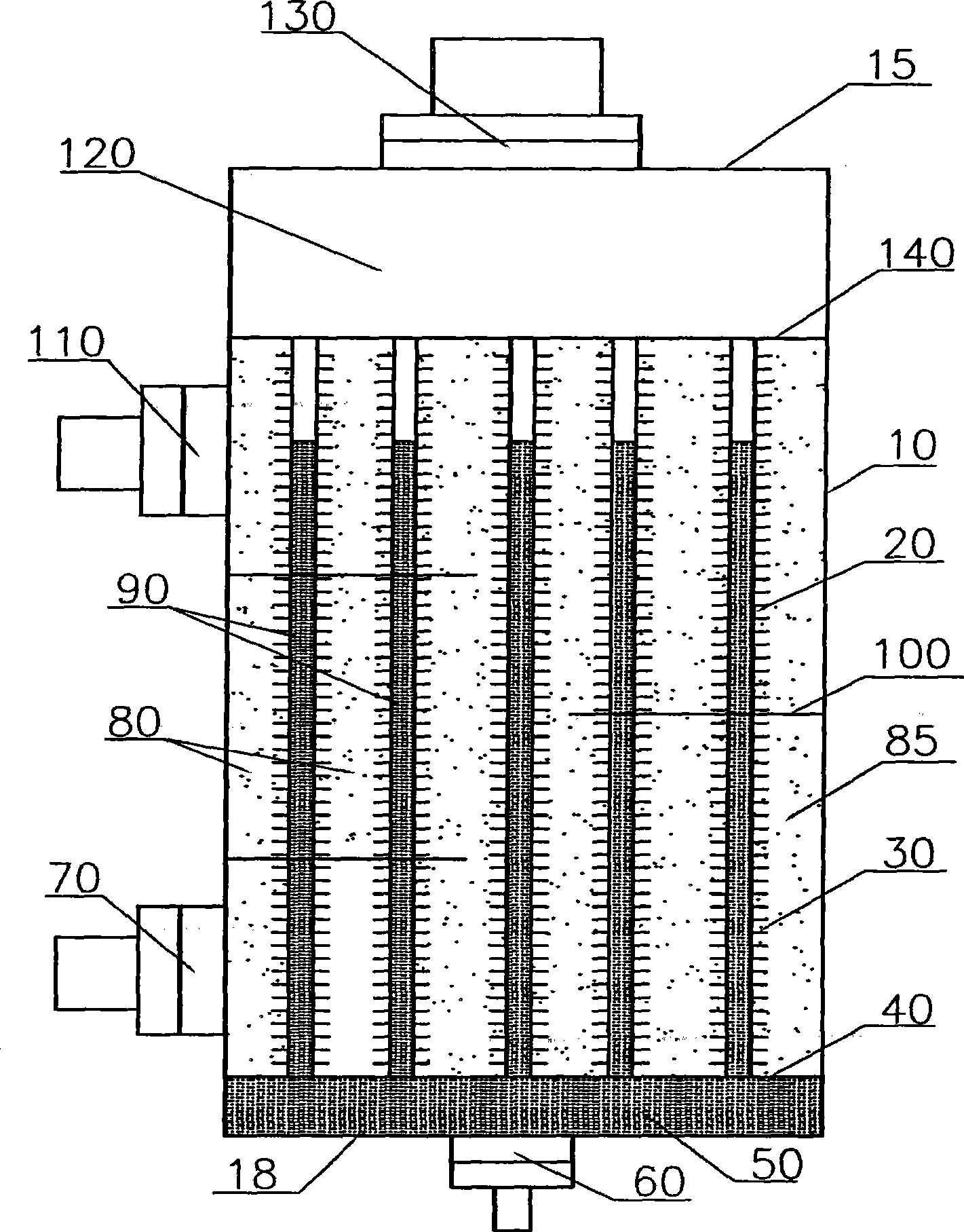
[0026] As shown in the drawings, the specific embodiment of the present invention consists of a sealed container shell wall 10, an upper top plate 15 of the sealed container, a lower bottom plate 18 of the sealed container, metal heat exchange tubes 20, tube fins 30, an oil-liquid separation bottom plate 40, and a liquid collection space. 50. Liquid inlet flange 60, oil outlet flange 70, transformer oil 80, oil chamber 85, evaporation liquid 90, tube side baffle 100, oil inlet flange 110, gas collection space 120, gas outlet flange 130, oil Separate the top plate 140 and other components.

[0027] The sealed container shell wall 10, the upper top plate 15 of the sealed container and the lower bottom plate 18 of the sealed container form the whole shell of the sealed container. A liquid collection space 50 is formed between the lower bottom pla...


PUM


Abstract

A transformer heat exchanger adopts the evaporative cooling technology, wherein transformer oil (80) enters into an oil chamber (85) through an oil inlet flange (110), and then flows out from an oil outlet flange (70) after exchanging heat with evaporating liquid (90) through a metal heat exchange tube (20), the evaporating liquid (90) is filled into a space which is formed by a liquid-collecting space (50) and the metal heat exchange tube (20), then is continuously heated up by heat transformer oil (80), and can absorb heat energy after boiling and vaporizing to generate phase change, thereby realizing the purposes of heat absorbing and cooling. Evaporating liquid steam which is generated through vaporizing upwards enters into a gas-collecting space (120) through the metal heat exchange tube (20), flows out the heat exchanger through a gas outlet flange (130), regenerates the phase change into liquid through the secondary cooling, and then returns to the liquid-collecting space (50) through a pipe, thereby finishing the circulation. The invention can increase the heat exchange efficiency, can not generate the transformer insulation accidents, even if the evaporating liquid leaks into the transformer oil owing to the higher electric insulation level of the evaporating liquid, thereby avoiding safety hidden dangers caused by the accident.

Description

technical field [0001] The invention relates to a transformer cooler, in particular to a transformer heat exchanger which adopts evaporative cooling technology to generate phase-change heat. Background technique [0002] Traditional transformer cooling methods generally include natural oil circulation air cooling, forced oil circulation air cooling, forced oil circulation water cooling, etc. The former one is only applicable to the case of a small capacity of a single machine. With the continuous increase of the capacity of a single transformer, its cooling method is increasingly dependent on the latter two. The coolers of the current large and medium-capacity power transformers are either fin radiators or air-cooled coolers, or water-cooled coolers, that is, air or water is used as the cooling medium to cool the transformer oil in operation through the heat exchanger. cool down. But no matter the fin radiator, air-cooled cooler or water-cooled cooler, there are inherent d...

Claims


Application Information

Patent Timeline
Patent Type & Authority Applications(China)
IPC IPC(8): H01F27/18H01F27/12H01F27/14
CPCF28D15/0275F28D15/02
Inventor 张国强牛文豪王新
Owner INST OF ELECTRICAL ENG CHINESE ACAD OF SCI
Why Eureka
Try Eureka