Wiring box

A junction box and box cover technology, which is applied in the field of junction boxes, can solve problems such as the temperature rise of the metal connector group, the increase in the cost of the junction box, and the complex structure of the heat dissipation metal sheet.

Active Publication Date: 2009-03-18
ZHEJIANG RENHE PHOTOVOLTAIC TECH
View PDF1 Cites 24 Cited by
  • Summary
  • Abstract
  • Description
  • Claims
  • Application Information

AI Technical Summary

Problems solved by technology

The heat dissipation metal sheet used in this solution has a complex structure, which is inconvenient to install and increases the cost of the junction box. Moreover, the heat dissipation metal sheet is located in the same airtight box as the diode and the metal connector group, and the heat dissipation effect is not ideal.
[0004] In this type of junction box in the prior art, the diode and the connected metal connector group are placed in the same chamber, and the heat generated by the diode is easily conducted to the metal connector group, which increases the temperature of the metal connector group. Affects the efficiency of electrical transmission

Method used


Image

  • Wiring box
  • Wiring box
  • Wiring box

Examples


Embodiment 1

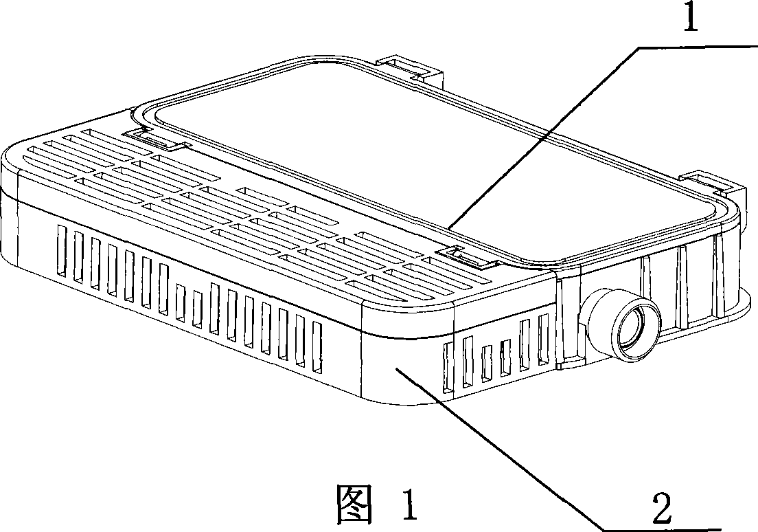
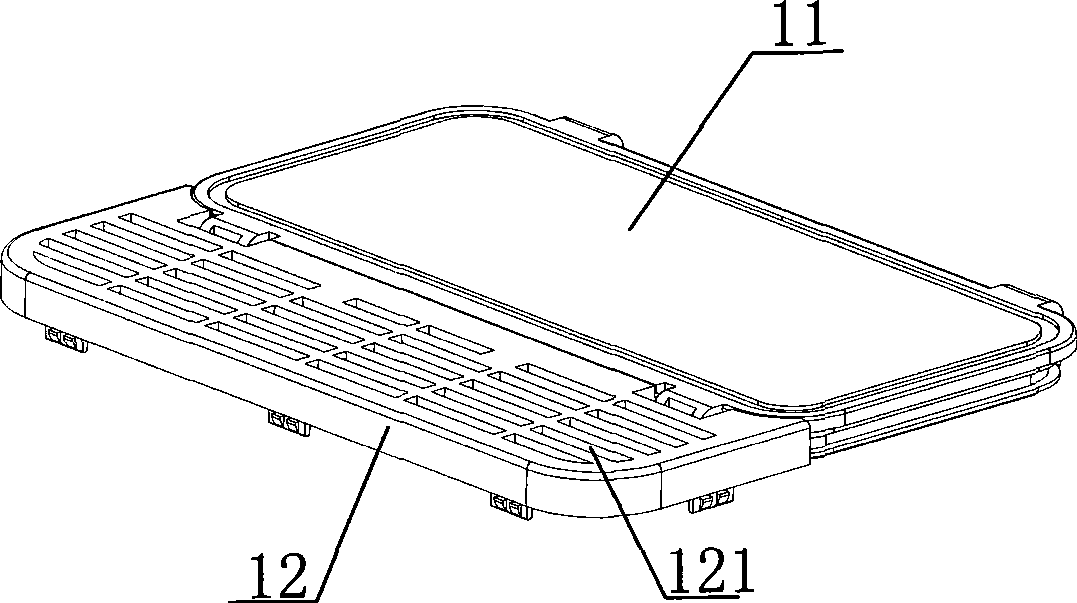
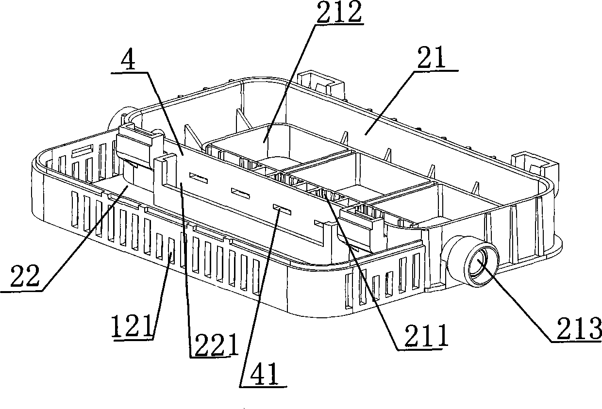
[0024] This embodiment relates to a junction box, which includes a box cover 1, a box body 2, and several parallel metal connectors 3. The box body 2 is divided into two chambers by a partition 4, which are respectively a closed chamber 21 and a heat dissipation chamber 22. A plurality of mounting grooves 211 are arranged side by side in the airtight chamber 21 close to the side of the partition 4, and the metal connector 3 is embedded in the installation groove 211. The bottom surface of the airtight chamber 21 away from the side of the partition 4 is provided with a hole 212. On the partition 4 There are two holes 41 corresponding to the metal connector 3; the box cover 1 is two, respectively an airtight cover 11 and a heat dissipation cover 12, which are matched with the corresponding airtight chamber 21 and heat dissipation chamber 22, and the sides of the heat dissipation chamber 22 or The heat dissipation cover 12 is provided with a heat dissipation hole 121 . The heat d...

Embodiment 2

[0027] Embodiment 2 is a further improvement on Embodiment 1. The improvement is that a glue injection groove 221 is provided in the cooling cavity 22 near the partition 4 along the length direction of the partition 4 .

[0028] The function of setting the glue injection groove 221 is to inject waterproof glue into the glue injection groove 221 when the diode template 5 is placed in the heat dissipation cavity 22 and passes through the hole 41 on the partition plate 4 to connect with the metal connector 3, and the hole 41 is airtight, which not only plays a waterproof role but also makes the diode template 5 and the metal connector 3 fully airtight.

Embodiment 3

[0030] Embodiment 3 is further improved on the basis of Embodiment 1. The improvement is that the outermost metal connector 3 is connected with a round tubular metal terminal 34, and the closed cavity 21 in the extending direction of the circular tubular metal terminal 34 is Wiring holes 213 are provided on the side. With this scheme, the distance from the connecting wire to the circular tubular metal terminal 34 is the shortest, and the connecting wire can be inserted into the circular tube during connection, making the connection more convenient and firm.


PUM


Abstract

The invention relates to a junction box, which comprises a box cover, a box body and a plurality of parallel metal connectors, and is characterized in that the box body is divided into two chambers by a baffle plate, and the two chambers are respectively a closing chamber and a radiating chamber, wherein a plurality of mounting grooves are mounted in the closing cavity in parallel near the baffle plate, the metal connectors are inlayed in the mounting grooves, the bottom surface of the closing cavity which is faraway from the baffle plate is provided with a hole, a hole is arranged on the baffle plate which is corresponding to the metal connectors, the number of the box cover is two, and the two box covers are respectively a closing cover and a radiating cover, and the closing cover and the radiating cover are matched with the closing cavity and the radiating cavity, and radiating holes are arranged on the lateral surface of the radiating cavity or the radiating cover. The junction box can radiate the portion which needs to radiate in the box body, and close the portion which needs to be closed, optimizes the property of the junction box, and can effectively improve the service span of the junction box.

Description

technical field [0001] The invention relates to an electrical accessory for converting solar energy into electrical energy, in particular to a junction box for connecting an electrical solar cell module with other components of a solar system. Background technique [0002] Solar power generation uses multiple groups of solar cell modules arranged in a matrix to convert sunlight into electrical energy. Each group of solar cell modules is connected to a junction box, and the junction box is then connected to other parts of the solar power generation system. The rationality and quality of the mechanical structure design of this junction box are directly related to the efficiency of electrical transmission. Since this kind of junction box works outdoors for a long time, it has high requirements on airtightness and heat dissipation. The existing junction boxes are generally completely airtight boxes. Although they have high airtightness and are suitable for field work, they are n...

Claims


Application Information

Patent Timeline
Patent Type & Authority Applications(China)
IPC IPC(8): H02G3/08H02G3/16H05K7/20
Inventor 励国庆
Owner ZHEJIANG RENHE PHOTOVOLTAIC TECH
Why Eureka
Try Eureka