
Accumulator charging system

A charging system and storage battery technology, applied to battery circuit devices, current collectors, electric vehicles, etc., can solve problems such as long charging time, increased volume, and unachievable unidirectional DC/DC, so as to improve energy utilization and charge The effect of fast discharge speed and good technical performance

Inactive Publication Date: 2009-03-18
INST OF ELECTRICAL ENG CHINESE ACAD OF SCI
View PDF2 Cites 47 Cited by
  • Summary
  • Abstract
  • Description
  • Claims
  • Application Information

AI Technical Summary

Problems solved by technology

The DC / DC step-down converter in this patent is unidirectional and cannot use Reflex TM method charging
[0012] The battery charging system involved in the existing patent either adopts the constant current charging method or the constant current / constant voltage charging method, which not only takes a long time to charge, but also has low efficiency
Existing battery charging systems using pulse charging, or using unidirectional DC / DC cannot achieve Reflex TM charging method, or feed back to the grid through the large capacitor of the bus bar; the former reduces the efficiency, although the latter improves the efficiency, but increases the size of the entire system, and the energy directly fed back to the grid will cause harmonic pollution to the grid
Therefore, in view of the current conventional charging method of rechargeable batteries that takes a long time, and the fast charging method will cause pollution or low efficiency to the power grid, and in view of the fast energy storage characteristics of supercapacitors, this patent proposes the use of DC / DC bidirectional Converter and supercapacitor bank to achieve reflex of battery TM Charging methods to improve system efficiency, reduce power levels, and avoid pollution to the grid

Method used


Image

  • Accumulator charging system
  • Accumulator charging system
  • Accumulator charging system

Examples


Embodiment Construction

[0025] The present invention will be further described below in conjunction with the accompanying drawings and specific embodiments.

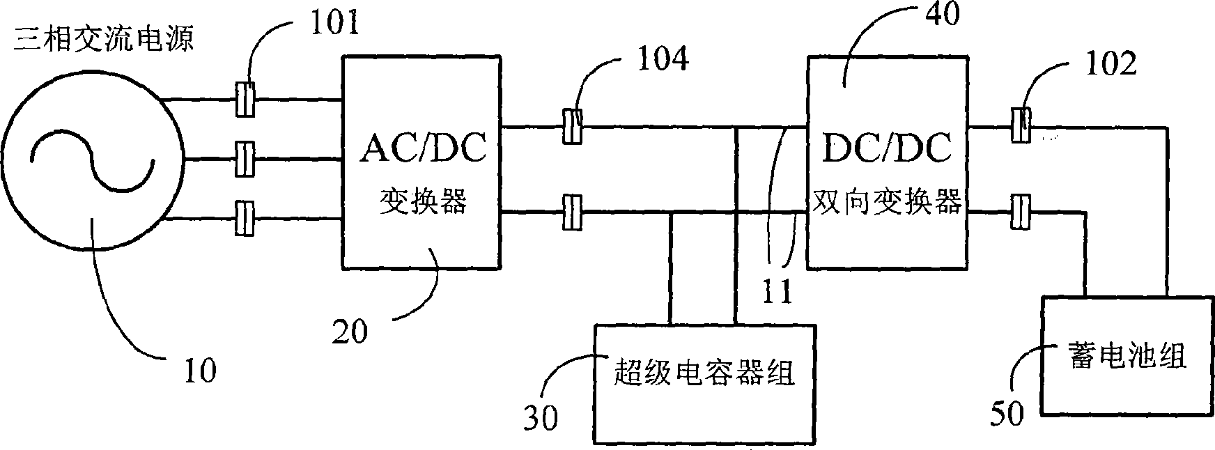
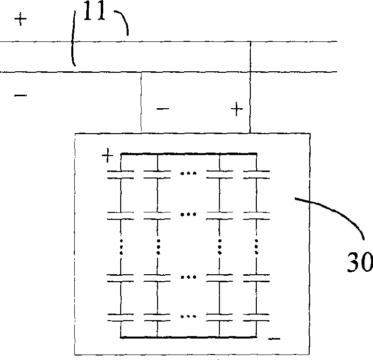
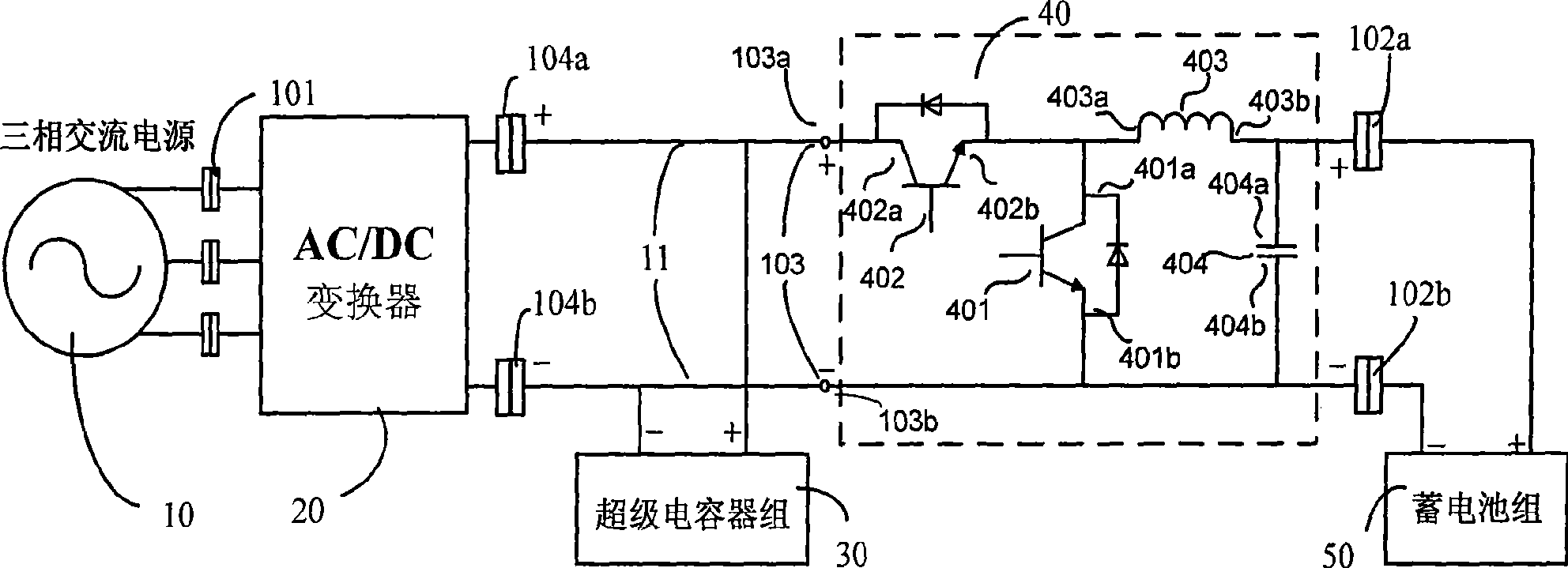
[0026] Such as figure 1 As shown, the novel battery charging system of the present invention includes a three-phase AC power supply 10, an AC / DC converter 20, a supercapacitor bank 30, a DC / DC bidirectional converter 40, a battery pack 50, and an electrical interface 101, a DC bus interface 104, Battery charging interface 102 . The supercapacitor bank 30 is connected to the DC / DC bidirectional converter 40 through the DC bus 11 . The DC / DC bidirectional converter 40 is connected to the battery pack 50 through the battery charging interface 102 . The three-phase AC power supply 10 is connected to the AC / DC converter 20 through an electrical interface 101 .

[0027]The three-phase alternating current generated by the three-phase alternating current power supply 10 passes through the electrical interface 101 , is rectified and stepped down by t...


PUM


Abstract

The invention relates to an accumulator charging system, which comprises a three-phase alternating current power supply (10), an AC / DC convertor (20), a super capacitor group (30), a DC / DC bidirectional convertor (40) and an accumulator group (50), wherein the super capacitor group (30) is connected with the DC / DC bidirectional convertor (40) through a direct current bus (11). The DC / DC bidirectional convertor (40) is connected with the accumulator group (50)through an accumulator charging interface (102). The three-phase alternating current power supply (10) is connected with the AC / DC convertor (20) through an electric interface (101). The accumulator charging system can achieve conventional charging mode which comprises constant current, constant voltage and the like through controlling the DC / DC bidirectional convertor (40), can further generate positive and negative current impulse whose amplitude and width can be adjusted, achieves pulse charge to the accumulator group (50), provides particle or full electric energy by the super capacitor group (30) in a positive-going pulse period, absorbs electricity in a negative-going pulse period, lowers the charging grade of a charging power supply, and improves the energy utilization efficiency of the accumulator charging system.

Description

technical field [0001] The invention relates to a storage battery charging system, in particular to a pulse charging system capable of rapidly charging the storage battery. Background technique [0002] Since Gaston Plante, a Frenchman, discovered the phenomenon of lead-acid charging and discharging in 1859, lead-acid batteries have been the most widely used products in the field of batteries, such as automobiles, locomotives, ships, airplanes, and backup power supply equipment. Acid batteries, and still occupy a dominant position, have an irreplaceable position. Especially in recent years, in consideration of environmental pollution and energy security, electric vehicle technology and renewable energy power generation technology have developed rapidly; various batteries including lead-acid batteries, nickel-cadmium batteries, lithium-ion batteries, etc. As a power source or a backup power source, how to charge efficiently and quickly has become one of the main tasks of bat...

Claims


Application Information

Patent Timeline
IPC IPC(8): H02J7/02
Inventor 张国驹唐西胜邓卫齐智平
Owner INST OF ELECTRICAL ENG CHINESE ACAD OF SCI
Learn More