
Gas purification method of low concentration organic compound

A technology for purification of organic compounds and gases, applied in chemical instruments and methods, separation methods, catalyst carriers, etc., can solve problems such as air pollution, odor, and inability to effectively purify

Inactive Publication Date: 2009-03-25
JG ENVIRONMENTAL TECH +1
View PDF0 Cites 18 Cited by
  • Summary
  • Abstract
  • Description
  • Claims
  • Application Information

AI Technical Summary

Problems solved by technology

At present, the most commonly used purification equipment in China is to deal with air extraction and simple filter screen or general adsorption or washing with water. This traditional equipment and method cannot effectively purify the gases containing sulfur compounds such as dimethyl sulfide and dimethyl disulfide. It is the main cause of air pollution and odor; at the same time, it is also the main cause of molecular pollutants that cause polluted outside air to enter high-end process clean rooms such as semiconductor chip manufacturing plants and TFT-LCD panel optoelectronic manufacturing plants. one of the sources

Method used


Image

  • Gas purification method of low concentration organic compound
  • Gas purification method of low concentration organic compound

Examples


Embodiment 1

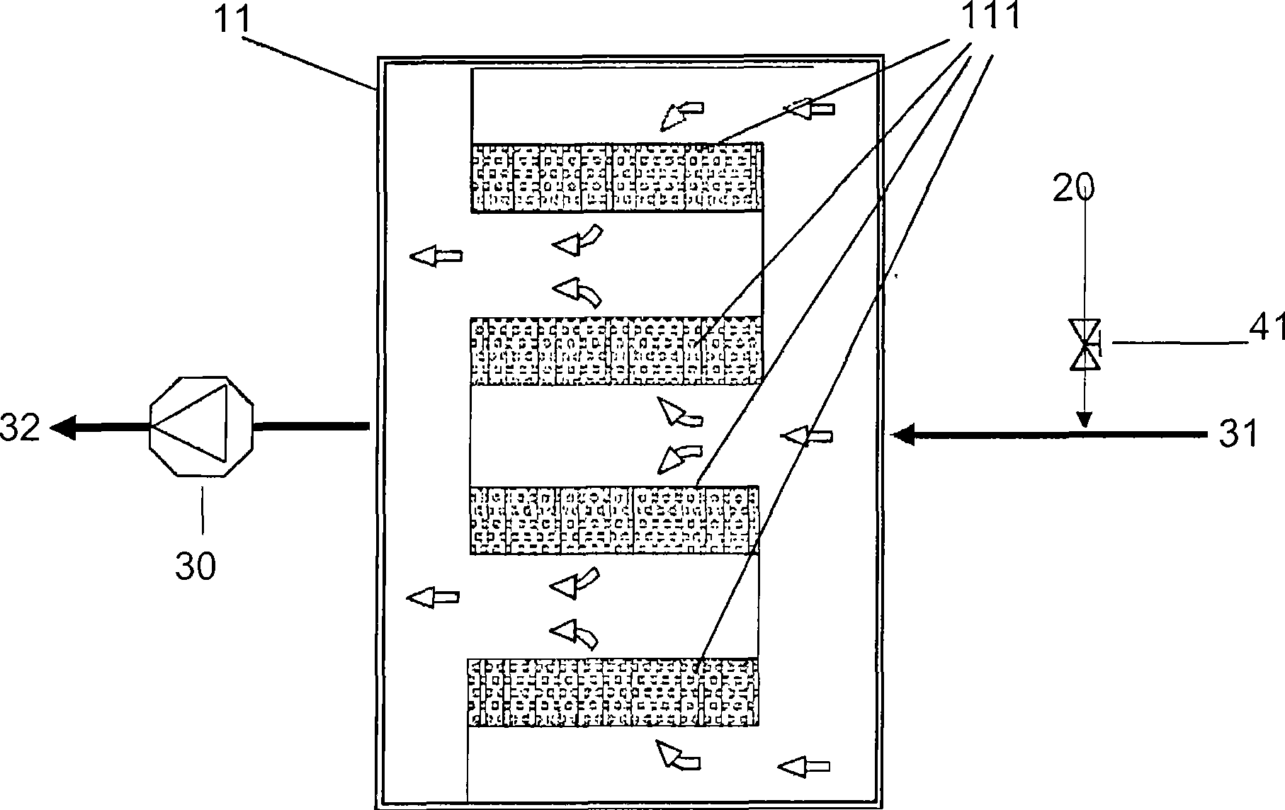
[0058] figure 1 It is a schematic diagram of a preferred embodiment of the gas purification device for low-concentration organic compounds in the air of the present invention. The device comprises a catalyst adsorption unit 11, which is filled with a catalyst adsorption material 111, and it is composed of a catalyst carrier and a catalyst, and the catalyst carrier is selected from activated carbon, zeolite, aluminum oxide, other porous substances or mixtures thereof; The active portion of the catalyst is N-orbit metal, which is selected from Mn, Fe, Co, Ni, Cu, Ag, Pb or Zn; The downstream end, which can pump the air to be treated to the catalyst adsorption unit 11 through the catalyst adsorption material 111; a control valve 41, which can control whether ozone needs to enter the catalyst adsorption unit 11 and the catalyst adsorption material 111; and an ozone The generating unit 20 can provide ozone to the catalyst adsorption unit 11 and the catalyst adsorption material 111...

Embodiment 2

[0061] Use the device described in embodiment 1, open fan 30, close valve 41, the gas of the low-concentration organic compound that can be processed in air inlet 31 can be introduced into catalyst adsorption unit 11 and catalyst adsorption material 111 through fan 30, carry out chemical Adsorption reaction, the clean gas after adsorption flows through a gas outlet 32 ​​to be discharged. Can choose to open valve 41 simultaneously, import the ozone that ozone generation unit 20 produces and regulate the concentration of ozone supply or generation, make the catalyst adsorption material 111 in the catalyst adsorption unit 11 that has carried out chemical adsorption before can carry out low temperature redox or and decomposition reaction, so as to prolong the service life and treatment efficiency of the catalyst adsorption material 111 filled inside the catalyst adsorption unit 11 , and the resulting net gas is discharged from the gas outlet 32 ​​.

[0062] After the catalyst adso...


PUM


Abstract

The invention discloses a gas purification method for treating low-concentration organic compounds, in particular to a gas purification method aiming at the following malodorous compounds such as sulfides of dimethyl sulfide (DMS), dimethyl disulfide (DMDS), sulfurated hydrogen (H2S) and the like as well as formaldehyde, acetic acid, isopropyl alcohol, acetone and the like. The method comprises: at least one catalyst adsorption unit in parallel connection and / or in series connection; and / or an ozone generating unit which can provide ozone to the catalyst adsorption unit to serve as a component that can strengthen the adsorption function of catalyst and is easy to be treated or is harmless after low temperature oxidation reduction or decomposition reaction, so as to greatly improve the treatment efficiency and extend the service life of the catalyst adsorption material.

Description

technical field [0001] The present invention discloses a gas purification method for treating low-concentration organic compounds, especially a gas purification method for containing the following malodorous compounds: such as dimethyl sulfide (DMS), dimethyl disulfide (DMDS), hydrogen sulfide (H 2 Gas purification method for sulfides such as S) and malodorous compounds such as formaldehyde, acetic acid, isopropanol, and acetone. The present invention is mainly used to increase catalyst efficiency, prolong catalyst life, and is suitable for purification of clean room air purification or waste gas emission in chip manufacturing with high air volume and low concentration, photovoltaic panel manufacturing, etc., and is also suitable for general wastewater It is used for air purification in factories, painting and printing industries and related chemical industries. Background technique [0002] Recently, the international community has paid more and more attention to environm...

Claims


Application Information

Patent Timeline
Patent Type & Authority Applications(China)
IPC IPC(8): B01D53/86B01D53/04B01D53/48B01J35/10B01J32/00
Inventor 张丰堂张智能
Owner JG ENVIRONMENTAL TECH
Learn More