Spiral chute conveyer

A conveyor and chute technology, applied in the field of conveyors, can solve the problems of high investment cost and daily use cost, noise generation, adverse environmental impact, etc., and achieve the goal of reducing investment cost, saving daily use cost, and improving the equipment use environment Effect

Inactive Publication Date: 2009-03-25
MIRACLE AUTOMATION ENG CO LTD
View PDF0 Cites 8 Cited by
  • Summary
  • Abstract
  • Description
  • Claims
  • Application Information

AI Technical Summary

Problems solved by technology

[0002] Most of the existing conveyors used to convey workpieces vertically downward adopt the structure of vertical elevators. Since vertical elevators need to install power drive units and flexible vertical traction units, the investment cost and daily use cost of equipment are high, and due to the power Noise will be generated when the unit operates, which will have a certain adverse effect on the surrounding environment

Method used


Image

  • Spiral chute conveyer

Examples


Embodiment Construction

[0008] The present invention will be further described below in conjunction with specific drawings and embodiments.

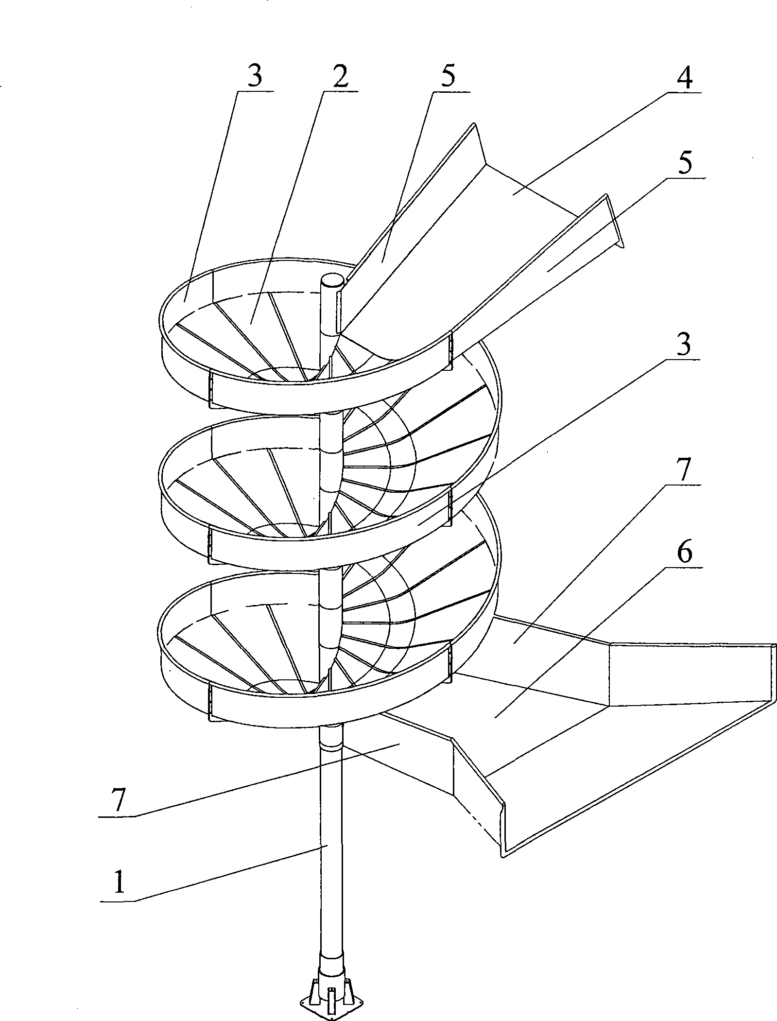
[0009] As shown in the figure: Install a spiral downward sloping slide plate 2 on the wall of the installation column 1, an upwardly protruding rib 3 is provided on the outer side of the slide plate 2, and a slideway inclined direction is provided at the top entrance of the slide plate 2. The chute inlet plate 4 provided below, the first baffle plate 5 is arranged on both sides of the chute inlet plate 4, the bottom end exit of the slide plate 2 is provided with the chute outlet plate 6 that the slideway is inclined downwardly, the chute Second baffles 7 are provided on both sides of the outlet plate 6 .

[0010] The chute inlet plate 4 is a plate with a gradually narrowing slideway from bottom to top, and the first baffle plate 5 close to the installation column 1 is arranged tangentially to the installation column 1 . The outlet plate 6 of the chute is a pla...


PUM


Abstract

The invention relates to a spiral chute conveyor used for vertically-downwards conveying work elements, belonging to the conveyor field. According to the technical proposal, a sliding plate with the downward sliding spiral is arranged on the wall of a mounting column; an upward projecting rib is arranged on the outer side of the sliding plate; a chute inlet plate provided with a downward slideway is arranged on the top inlet of the sliding plate; a first block plate is respectively arranged on two sides of the chute inlet plate; a chute outlet plate provided with the downward slideway is arranged on the bottom outlet of the sliding plate; a second block plate is respectively arranged on two sides of the chute outlet plate. Compared with the existing vertical lifter used for vertically-downwards conveying work elements, the spiral chute conveyor can largely reduce the investment cost of apparatus, saves the daily use cost and can largely improve the apparatus use environment.

Description

technical field [0001] The invention relates to a spiral chute conveyor used for vertically downward conveying of workpieces in the field of conveyors. Background technique [0002] Most of the existing conveyors used to convey workpieces vertically downward adopt the structure of vertical elevators. Since vertical elevators need to install power drive units and flexible vertical traction units, the investment cost and daily use cost of equipment are high, and due to the power Noise will be generated when the unit operates, which will have certain adverse effects on the surrounding environment. Contents of the invention [0003] The object of the present invention is to overcome the deficiencies in the prior art and provide a spiral chute conveyor with simple structure, low investment cost and daily use cost, and low noise when transporting workpieces. [0004] According to the technical solution provided by the present invention, a spiral downwardly inclined slide plate ...

Claims


Application Information

Patent Timeline
Patent Type & Authority Applications(China)
IPC IPC(8): B65G11/06B65G11/18
Inventor 张华兵孟宜春
Owner MIRACLE AUTOMATION ENG CO LTD
Why Eureka
Try Eureka