Half- penetration and half-reflection LCD

A semi-transmissive, semi-reflective, liquid crystal display technology, applied to static indicators, instruments, nonlinear optics, etc., can solve the problem of high cost of semi-transmissive, semi-reflective liquid crystal displays, achieve increased inclination and twist, and increase birefringence efficiency and cost reduction

Inactive Publication Date: 2009-03-25
INNOCOM TECH SHENZHEN +1
View PDF0 Cites 23 Cited by
  • Summary
  • Abstract
  • Description
  • Claims
  • Application Information

AI Technical Summary

Problems solved by technology

[0010] In order to solve the problem of high cost of transflective liquid crystal display, it is necessary to provide a transflective liquid crystal display with low cost without using internal retarder

Method used


Image

  • Half- penetration and half-reflection LCD
  • Half- penetration and half-reflection LCD
  • Half- penetration and half-reflection LCD

Examples


Embodiment Construction

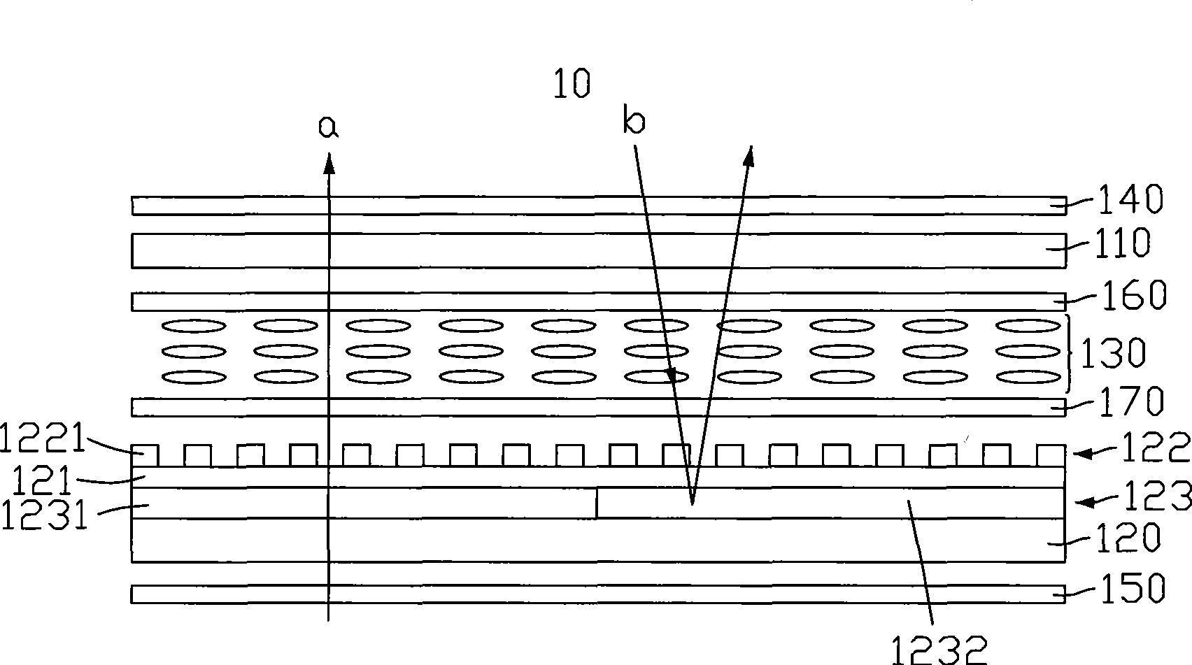
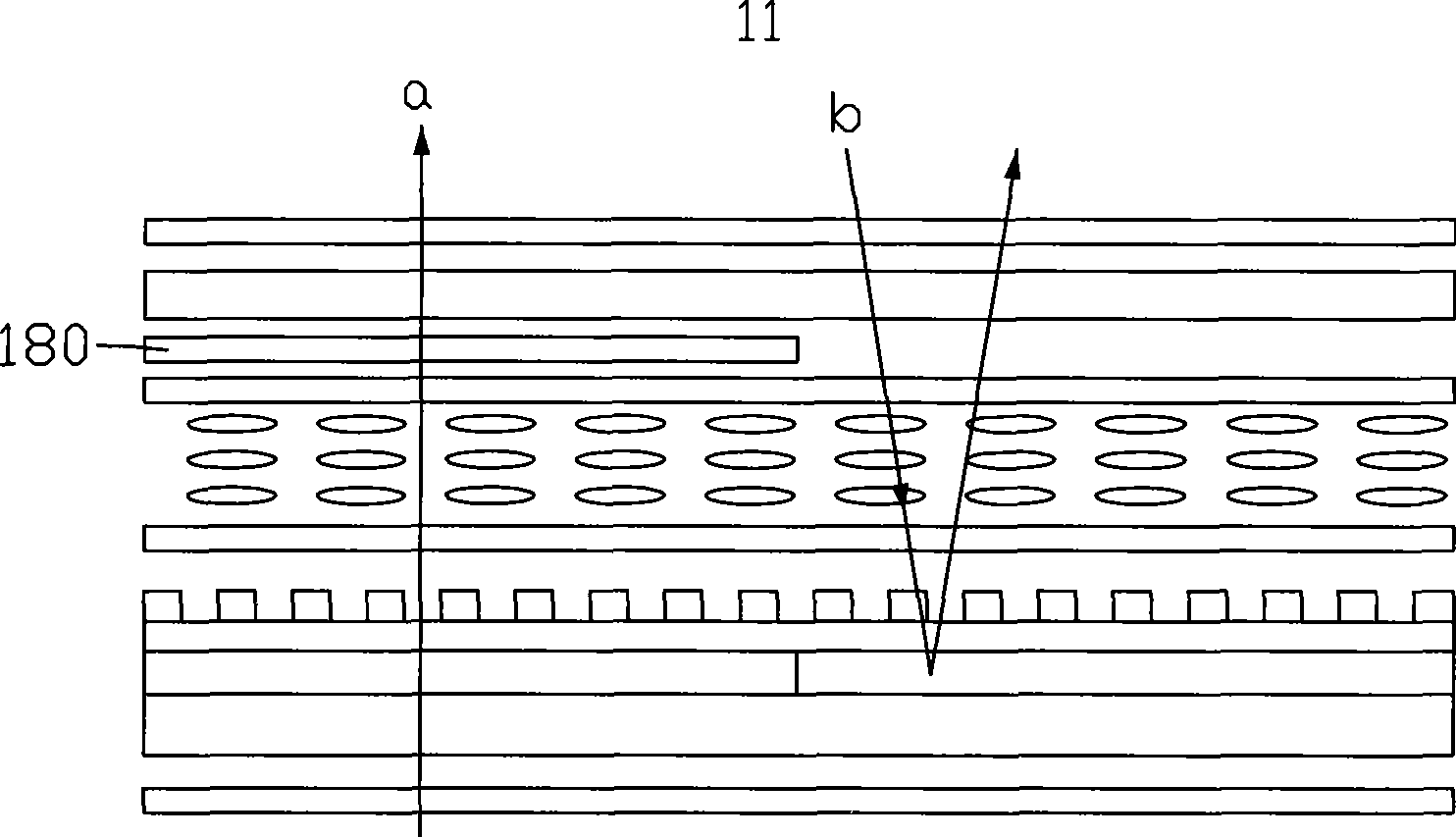
[0022] see Figure 5 , is a schematic diagram of the first embodiment of the transflective liquid crystal display of the present invention. The liquid crystal display 20 includes a first glass substrate 210, a second glass substrate 220 opposite to the first glass substrate 210, a liquid crystal layer 230 sandwiched between the two glass substrates 210, 220, a A first polarizer 240 on the outer surface of the glass substrate 210, a second polarizer 250 on the outer surface of the second glass substrate 220, a control electrode layer 280 on the inner surface of the first glass substrate 210 and a first The alignment layer 260 , a common electrode layer 223 , an insulating layer 221 , a pixel electrode layer 222 and a second alignment layer 270 are sequentially located on the inner surface of the second glass substrate 220 .

[0023] The common electrode layer 223 includes a transmissive region 2231 and a reflective region 2232 . The control electrode layer 280 is located on t...


PUM

PropertyMeasurementUnit
widthaaaaaaaaaa

Abstract

The invention relates to a transflective LCD, which comprises a first substrate, a second substrate opposite to the first substrate, a liquid crystal layer between the first substrate and the second substrate, a first polaroid sheet arranged on the surface of the outside of the first substrate, a second polaroid sheet arranged on the surface of the outside of the second substrate, a common electrode layer, an insulating layer, a pixel electrode layer and a second alignment layer which are arranged on the surface of the inside of the second substrate in order, and a control electrode layer and a first alignment layer which are arranged on the surface of the inside of the first substrate, wherein the common electrode layer comprises a transmittance zone and a reflective zone; the control electrode layer is positioned in a zone corresponding to the transmittance zone, and is applied with a voltage, so that the inclination angle of liquid crystal molecules corresponding to the transmittance zone is larger than that of liquid crystal molecules corresponding to the reflective zone, and the birefringence of the liquid crystal molecules corresponding to the transmittance zone is improved. The transflective LCD does not need an internal delay chip to reduce the cost.

Description

technical field [0001] The invention relates to a transflective liquid crystal display, in particular to a fringe electric field switch type transflective liquid crystal display. Background technique [0002] Liquid crystal displays are widely used because of their low radiation, light, thin and small size, and low power consumption. With the maturity and innovation of related technologies, their types are also becoming more and more diverse. [0003] According to different light sources used, liquid crystal display devices can be divided into transmissive liquid crystal display devices and reflective liquid crystal display devices. The transmissive liquid crystal display device must set a backlight on the back of the liquid crystal display panel to realize image display, however, the energy consumption of the backlight accounts for about half of the energy consumption of the entire transmissive liquid crystal display device, so the power consumption of the transmissive liqu...

Claims


Application Information

Patent Timeline
Patent Type & Authority Applications(China)
IPC IPC(8): G02F1/133G02F1/1343G02F1/1335G02F1/13363
Inventor 陈俊吉凌维仪陈鹊如杨秋莲
Owner INNOCOM TECH SHENZHEN
Why Eureka
Try Eureka