Reconfigurable antenna

A technology for reconfiguring antennas and antenna radiation, applied to antennas, resonant antennas, and devices that enable antennas to work in different bands at the same time, can solve the problem of low bandwidth gain of antennas, and achieve reduced number of switches, high antenna gain, and distributed uniform effect

Inactive Publication Date: 2009-03-25
SHANGHAI JIAO TONG UNIV
View PDF0 Cites 23 Cited by
  • Summary
  • Abstract
  • Description
  • Claims
  • Application Information

AI Technical Summary

Problems solved by technology

[0003] Found through document retrieval to prior art, in 2007 Chih-Yu Huang etc. published "PlanarUltral-Wideband Antenna with a Frequency Notch Characteristic (with frequency Planar Ultra-Wideband Antenna with Traps)" proposed a circular monopole ultra-wideband antenna that can work at 1GHz to 11GHz, and by opening a sector-shaped gap on the circular patch, it can have a very wide range while maintaining ultra-wideband characteristics. Narrow band-stop characteristics, but the gain of the antenna in the working bandwidth is very low, up to 3dBi

Method used


Image

  • Reconfigurable antenna
  • Reconfigurable antenna
  • Reconfigurable antenna

Examples


Embodiment Construction

[0023] The embodiments of the present invention are described in detail below in conjunction with the accompanying drawings: this embodiment is implemented on the premise of the technical solution of the present invention, and detailed implementation methods and specific operating procedures are provided, but the protection scope of the present invention is not limited to the following the described embodiment.

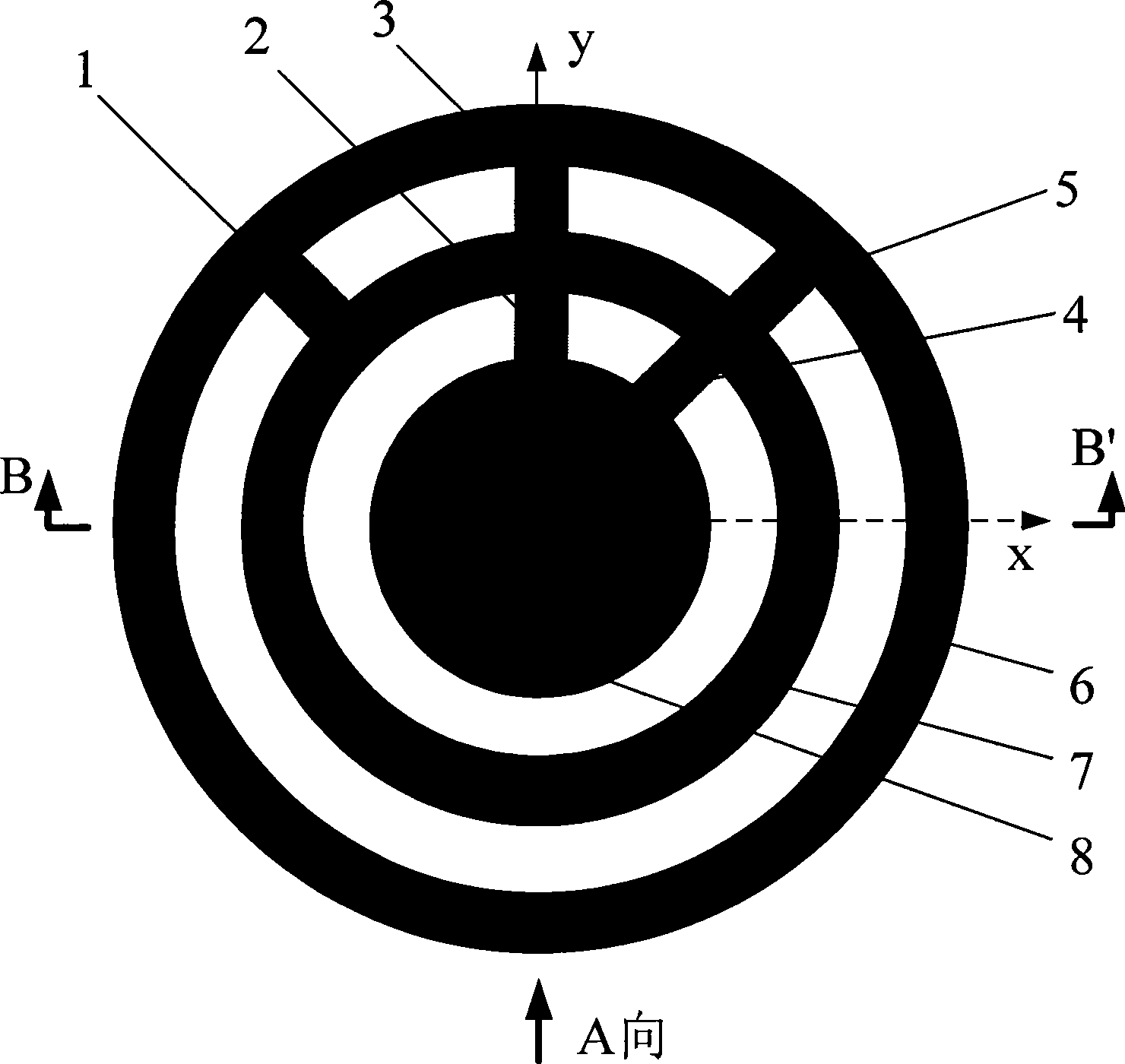
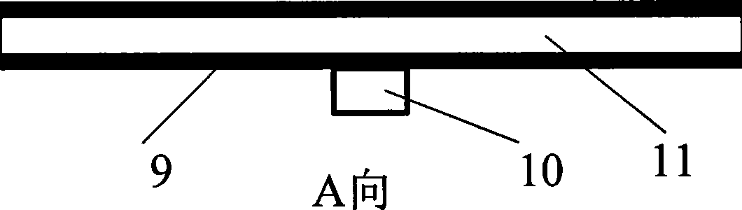
[0024] Such as figure 1 , figure 2 , image 3 and Figure 4 As shown, this embodiment includes: a first radio frequency switch 1, a second radio frequency switch 2, a third radio frequency switch 3, a fourth radio frequency switch 4, a fifth radio frequency switch 5, a first antenna radiation unit 6, and a second antenna radiation unit 7. The third antenna radiating unit 8 , the ground plate 9 , the feed port 10 , the dielectric plate 11 , five common connecting wires 12 , 13 , 14 , 15 , 16 and the switch controller 17 .

[0025] The first antenna radiating unit ...


PUM


Abstract

A reconfigurable antenna is used in the technical field of the wireless communication. The antenna comprises three antenna radiation units, a grounding plate, a feeding port, a medium plate, five radio frequency switches, a switch controller and an ordinary connecting wire. The antenna radiation units are concentric circular sheets and circular rings which are positioned on the same side of the medium plate. The feeding port is connected with a center radiation unit of each antenna radiation unit. The five radio frequency switches are connected with the three radiation units. The ordinary connecting wire respectively connects the radio frequency switches with the switch controller, so that the connection or the disconnection of each radio frequency switch can be controlled through the switch controller, thereby changing different connection states among the three radiation units and realizing the work of the antenna in different frequency bands, namely frequency reconfiguration. The reconfigurable antenna is used for sending and receiving electromagnetic waves, and has simple structure, small volume of the whole structure, and wide reconfigured frequency band; and the control of working frequency can be realized through digital coding.

Description

technical field [0001] The invention relates to an antenna used in the technical field of communication, especially a reconfigurable antenna. Background technique [0002] In the prior art, narrowband antennas are generally used in communication or radar, but it is difficult to meet the efficient utilization of spectrum resources and high-speed information transmission. In recent years, some people have begun to use ultra-wideband antennas, but the gain is very low and the pattern is unstable. [0003] Found through document retrieval to prior art, in 2007 Chih-Yu Huang etc. published "PlanarUltral-Wideband Antenna with a Frequency Notch Characteristic (with frequency Planar Ultra-Wideband Antenna with Traps)" proposed a circular monopole ultra-wideband antenna that can work at 1GHz to 11GHz, and by opening a sector-shaped gap on the circular patch, it can have a very wide range while maintaining ultra-wideband characteristics. Narrow band-stop characteristics, but the gai...

Claims


Application Information

Patent Timeline
Patent Type & Authority Applications(China)
IPC IPC(8): H01Q1/38H01Q5/00H01Q9/04H01Q23/00H01Q5/321
Inventor 耿军平金荣洪丁天金耀
Owner SHANGHAI JIAO TONG UNIV
Why Eureka
Try Eureka