Supercharge Your Innovation With Domain-Expert AI Agents!

Pulse width modulating control circuit applied to capacitor charging

A pulse width modulation and control circuit technology, applied in the direction of adjusting electrical variables, control/regulation systems, and conversion equipment with intermediate conversion to AC, can solve the problem of prolonged charging time of the output capacitor Co

Inactive Publication Date: 2009-03-25
LEADTREND TECH
View PDF0 Cites 12 Cited by
  • Summary
  • Abstract
  • Description
  • Claims
  • Application Information

AI Technical Summary

Problems solved by technology

like figure 2 As shown, when the power switch SW is turned off, the secondary side current Is of the transformer 40 gradually drops to zero, but when the drain voltage Vsw of the power switch SW drops to the second reference voltage Vref2 due to resonance, the power switch SW turns on again. In this way, a blank time Tb will be generated, and the proportion of the blank time Tb to the off-time Toff of the power switch SW will be longer as the drain voltage Vsw is higher (the drain voltage Vsw is approximately proportional to the output voltage Vout), because The primary side current Ip is negative during this blank time, so the average charging current Iin decreases with the increase of the output voltage Vout, so when the voltage of the output capacitor Co is closer to the target value, the average charging current Iin is lower, which will cause The charging time of the output capacitor Co increases

Method used


Image

  • Pulse width modulating control circuit applied to capacitor charging
  • Pulse width modulating control circuit applied to capacitor charging
  • Pulse width modulating control circuit applied to capacitor charging

Examples


Embodiment Construction

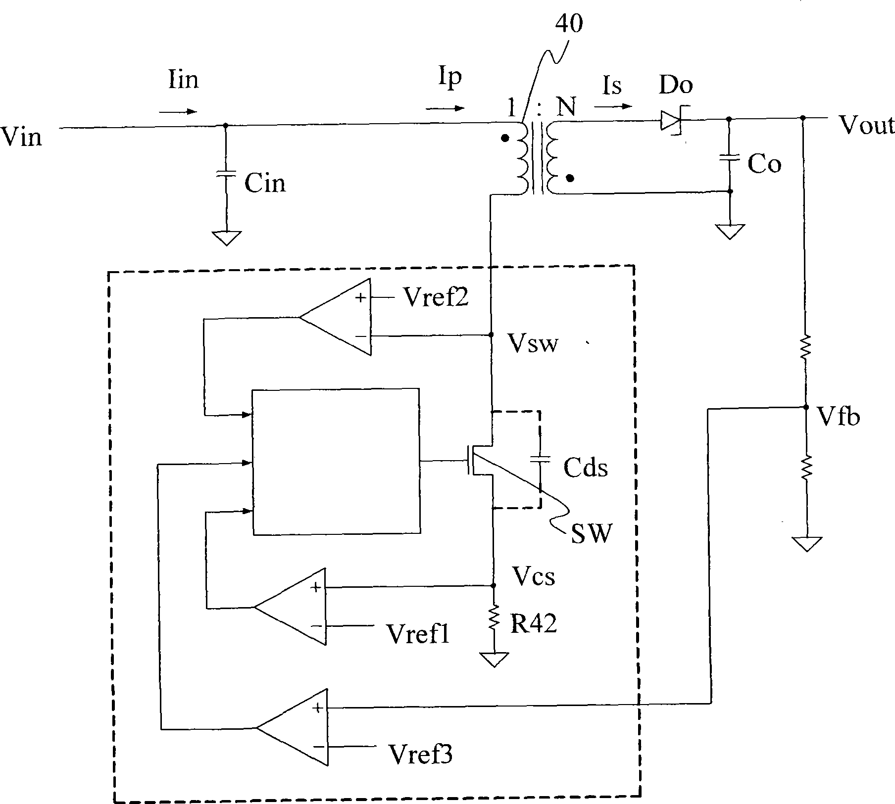
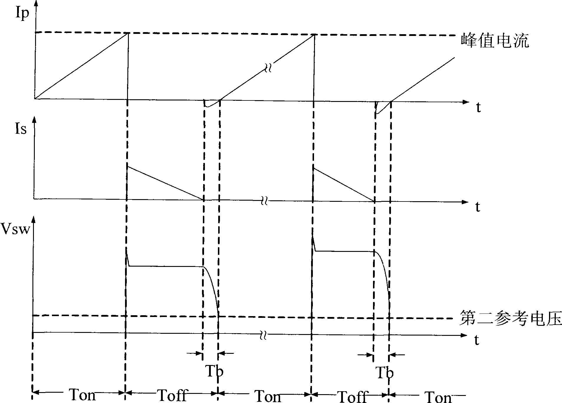
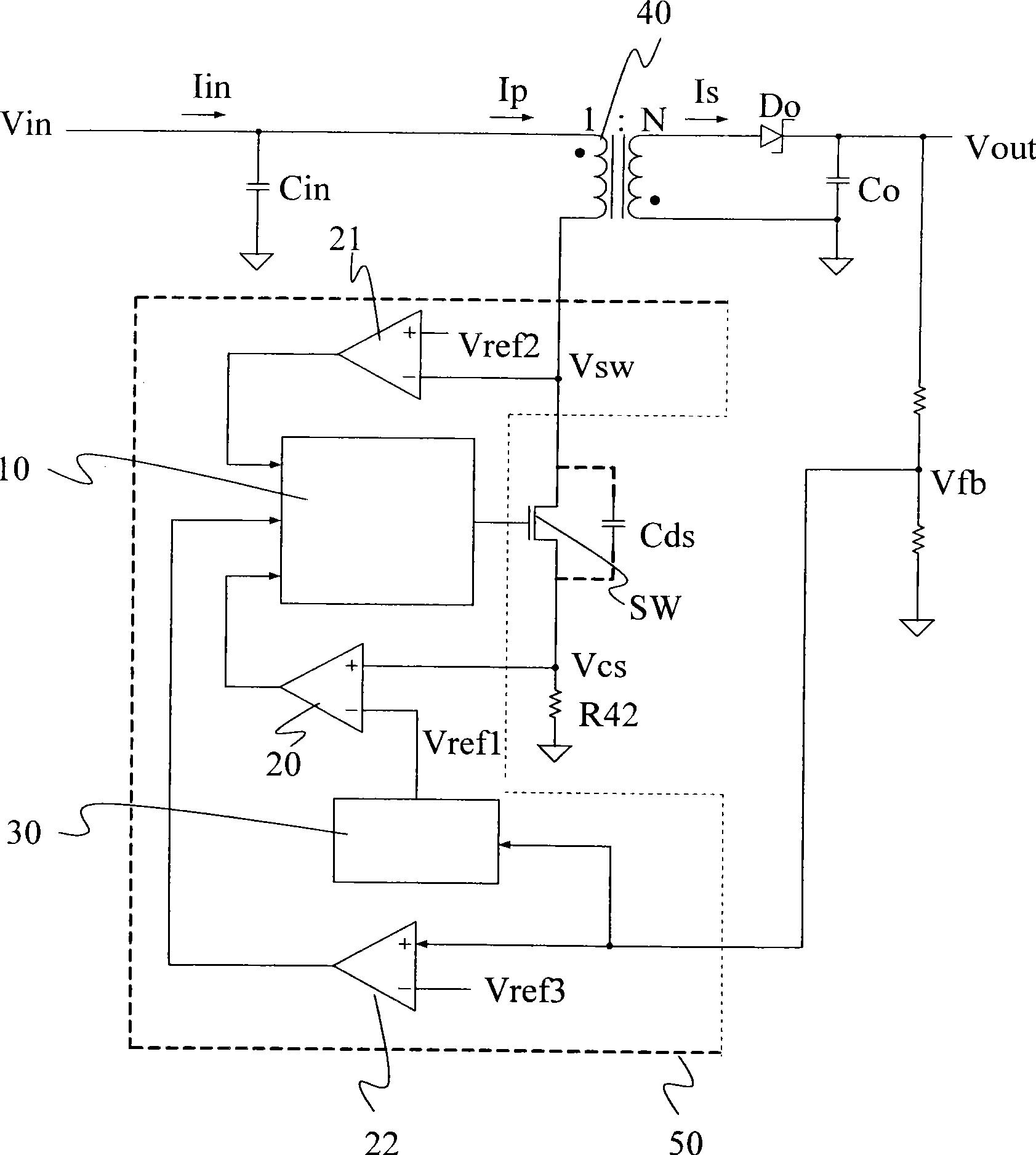
[0069] Please refer to Figure 3A, is a schematic circuit diagram of the first embodiment of the present invention. like Figure 3A As shown, the pulse width modulation control circuit 50 of the present invention includes a pulse width modulation signal generator 10, a first comparator 20, a second comparator 21, a third comparator 22 and a reference voltage regulator 30, wherein the pulse The width modulation control circuit 50 may be formed by, for example, an integrated circuit (IC), and the pulse width modulation control circuit 50 may also include a power switch SW and a resistor R42.

[0070] The pulse width modulation signal generator 10 generates a pulse width modulation signal according to the input control signal, and outputs the pulse width modulation signal to the power switch SW to control the power switch SW of the power converter, wherein the power switch SW can be, for example, is a metal oxide semiconductor (mos) switch, and the power switch SW has a parasit...


PUM


Abstract

A pulse width modulation controlling circuit is applied to a power converter charged by a capacitor, and comprises a pulse width modulation signal generator, a first comparator and a reference voltage adjuster, wherein the pulse width modulation signal generator is used for generating a pulse width modulation signal to control a power switch of the power converter; a first input terminal of the first comparator receives a first reference voltage, and a second input terminal thereof receives a sensing voltage proportional to a primary side current of a transformer of the power converter; when the power switch is turned on and the sensing voltage reaches the potential of the first reference voltage, a first control signal is output by the first comparator to the pulse width modulation signal generator, and a signal which enables the power switch to be turned off is output by the pulse width modulation signal generator; and the reference voltage adjuster outputs the first reference voltage according to a feedback voltage relevant to the output voltage of the power converter.

Description

technical field [0001] The invention relates to a pulse width modulation control circuit, in particular to a pulse width modulation control circuit applied to capacitor charging. Background technique [0002] In the field of digital cameras, sometimes when the user uses the camera, the light at the place where the user shoots the image is insufficient, and the flashlight needs to provide additional light to obtain a better photographic effect. However, the working voltage of the flash tube (generally about 300V) is much higher than the voltage of the internal battery of the camera (for example: the working voltage of a lithium battery is about 3V to 4.2V, and the working voltage of two AA batteries is about 2V to 3V). [0003] At this time, there is a high-voltage charging circuit inside the camera, using a flyback structure, and using a transformer with a high turn ratio (because the camera is thin and short, the turn ratio is about 10 times) to charge the high-voltage capa...

Claims


Application Information

Patent Timeline
Patent Type & Authority Applications(China)
IPC IPC(8): H02M3/28H02M3/335
Inventor 朱益杉王昱斌赵兴国
Owner LEADTREND TECH
Features
  • R&D
  • Intellectual Property
  • Life Sciences
  • Materials
  • Tech Scout
  • Unparalleled Data Quality
  • Higher Quality Content
  • 60% Fewer Hallucinations
Learn More